

 GPS & GNSS
 Lidar scanning
 Total Station
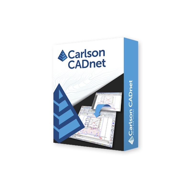
Carlson CADnet PDF BIM and Raster to CAD Conversion Software
Get the best price for your setup
Contact our experts for the best possible price and configuration.
- Fast response
- Expert configuration advice
- No overpaying for features you do not need
Carlson CADNet can be purchased as a standalone module or as part of the Takeoff Suite which also includes Construction, GeoTech and Trench. It can run standalone with the included license of IntelliCAD or on top of a separately purchased license of full AutoCAD.
Part of the Takeoff Suite, Carlson CADnet allows users to create CAD from non-CAD documents such as PDFs, raster images, vector images, and paper plans. CAD text can also be generated from raster images with CADnet’s built-in Optical Character Recognition (OCR). CADnet gives users the ability to import BIM models (doors, windows, walls, roofs, etc.) and bring them into CAD as CAD entities; plus, CADnet includes a routine to export surfaces into BIM. Carlson CADnet supports AutoCAD® and comes with IntelliCAD® built-in. This is in addition to working on legacy AutoCAD versions.
You may also like…




Valued customers:










Find RTK Networks
Search NTRIP providers and connect to reliable RTK correction services.
Description
Carlson CADnet for converting plans and images into CAD
Carlson CADnet is designed for professionals who regularly receive project information that is not supplied as clean, editable CAD data. It provides tools for turning PDF drawings, scanned plans, raster images and paper plans into useful CAD geometry so the information can continue into surveying, civil engineering, construction estimating or design workflows.
Instead of redrawing an entire project manually, users can trace and digitise the information that matters and convert it into standard CAD entities. CADnet also supports BIM workflows, allowing model information to be brought into the CAD environment and Carlson surface information to be prepared for BIM-based projects.
Convert PDF drawings into editable CAD information
PDF plans are common in tender documents, archived projects and drawings supplied by clients, but a PDF is not always suitable for direct survey or engineering work. Carlson CADnet provides tools for bringing these plans into the CAD environment and converting useful drawing information into editable entities.
Automatic tracing can help identify linework in suitable PDF drawings, reducing the amount of manual redrawing required. Once converted, lines and other entities can be edited, elevated, measured or incorporated into the rest of the project drawing.
This can be especially useful for construction estimators and surveyors who receive a PDF rather than the engineer’s original DWG file. The plan can be converted into working CAD information before quantities, layout data or design geometry are prepared.
Work with scanned plans and raster images
Older projects and tender documents may only exist as scanned drawings, photographs or raster image files. CADnet includes raster handling tools that allow this information to be used as the basis for new CAD geometry.
Users can trace raster linework, snap to information visible in the image and create standard CAD entities over the original plan. Raster editing tools can also be used to clean up source images by working with unwanted areas, speckles and line thickness before tracing.
For companies working with archived drawings, this provides a practical way to bring older information into a modern CAD workflow without recreating the entire drawing from measurements or manual coordinate entry.
Extract text from raster drawings
Carlson CADnet includes Optical Character Recognition tools for converting suitable text visible in raster images into CAD text entities. This can reduce the amount of manual typing required when a scanned plan contains elevations, labels, notes or other text that needs to become part of the editable drawing.
The result will naturally depend on the quality and clarity of the source image, so extracted information should still be reviewed before it is relied on for design or field preparation. On clear plans, however, OCR can make document conversion substantially quicker than manually re-entering every annotation.
Digitise directly from paper plans or on screen
CADnet provides a full set of digitising routines for project information that cannot be converted automatically. Users can digitise points, polylines, areas, contours, profiles, sections and end areas from source plans.
For a surveyor, this may mean extracting historic contours or boundaries from an old plan. A construction estimator may digitise proposed surfaces or material areas from tender drawings. A civil engineering team can recreate profiles and sections needed to continue a design when the original digital project data is unavailable.
By using dedicated routines for different types of geometry, the resulting drawing can contain more useful engineering information than a simple visual trace of the source plan.
Create CAD linework for estimating and construction preparation
CADnet is also one of the modules used within Carlson’s Takeoff workflow. This is important for earthwork and construction users because quantity calculations depend on having usable geometry and elevations rather than simply viewing a PDF in the background.
A contractor can start with a plan supplied as PDF or raster imagery, create the required CAD linework and then continue into surface modelling, quantity calculations or construction data preparation with other Carlson modules. This avoids having to rebuild the same project in unrelated software packages at each stage.
Import BIM information into CAD
Modern building and infrastructure projects increasingly combine CAD and BIM information. Carlson CADnet provides tools for bringing BIM model information into the CAD environment so elements such as walls, doors, windows and roofs can be represented as CAD entities.
This is useful when a surveyor, estimator or civil engineering professional does not need to work inside the complete authoring environment used to create the building model, but still needs relevant geometry for coordination, measurement or drawing production.
CADnet supports IFC-based BIM workflows, helping information move between BIM-oriented project teams and the CAD environment used for surveying or construction preparation.
Export Carlson surface information for BIM workflows
The workflow can also move in the other direction. CADnet includes functionality for exporting Carlson surface information for use in BIM-oriented projects.
For civil and surveying teams, this can help communicate terrain or site information to architects, structural designers and other project partners working with BIM. A surface prepared from survey or design data can therefore become part of a wider coordinated project model rather than remaining isolated in a separate CAD drawing.
Useful when the original DWG is unavailable
The strongest use case for CADnet is often a simple one: the drawing you need exists, but not in an editable format. A contractor may receive only a PDF tender set, a survey company may need information from a scanned historic plan, or an engineer may need to recover geometry from archived project documents.
CADnet gives these users tools to convert the source material into geometry that can be measured, edited and passed into normal CAD workflows. This can reduce repetitive drafting and provides more control over how legacy or client-supplied information is incorporated into a new project.
Practical applications for surveyors
Surveyors can use Carlson CADnet to recover useful design and reference information from plans before going into the field or while preparing a final drawing. Existing points, contours, boundaries or alignment information can be digitised and combined with newly collected GNSS or total station measurements.
It can also help when comparing an older design or record drawing with current field data. Rather than working from an image alone, important information from the historic plan can be converted into standard drawing entities and overlaid with the new survey.
Practical applications for construction professionals
Construction estimators and data-preparation teams often receive drawings from multiple consultants in different formats. CADnet provides a common conversion step before that data is used for earthwork estimating, site layout or machine-control preparation.
For example, proposed contours shown only on a tender PDF can be digitised into CAD geometry. Areas representing pavement or other materials can be traced for further quantity work, while building and site information from BIM can be brought into the drawing for coordination with civil data.
Practical applications for civil engineers and CAD technicians
Civil engineers and CAD technicians can use CADnet for document conversion, drawing reconstruction and coordination between CAD and BIM environments. This is particularly useful on refurbishment, redevelopment and infrastructure projects where historical information may exist in several generations of file formats.
Instead of treating every non-CAD document as a static reference, the important content can be selectively converted into standard drawing information and then cleaned, edited and incorporated into the current design.
Runs with IntelliCAD or AutoCAD
Carlson CADnet is part of Carlson’s CAD-based office software environment. The current Carlson 2026 installation supports CADnet and can operate with the included IntelliCAD platform or with a supported full AutoCAD installation.
This gives companies flexibility in how they deploy the software. A business that does not already use AutoCAD can work with the included IntelliCAD environment, while organisations with an established AutoCAD workflow can use CADnet with their supported installation.
Standalone module and wider Carlson workflow
CADnet can be used as a focused conversion and digitising module, but its value also extends into the wider Carlson software environment. It forms part of the Carlson Takeoff Suite alongside Carlson Construction, Trench and GeoTech, and it is also an eligible module within Carlson Select Suite.
For companies already using Carlson Survey, Civil, Construction or other office products, converted information can therefore continue into established surveying, engineering or estimating workflows rather than being exported and rebuilt in an unrelated system.
Who uses Carlson CADnet?
Carlson CADnet is suited to land surveyors, construction estimators, civil engineers, CAD technicians, contractors and other professionals who regularly receive project information in PDF, raster, paper-plan or BIM formats. It is particularly relevant where converting existing documents into editable project data is a regular part of office preparation.
A survey company may use it to recover information from historic plans, an estimator to build usable CAD geometry from tender drawings, and a civil engineering team to exchange information between CAD and BIM-based project workflows.
Carlson CADnet from Global GPS Systems
Global GPS Systems can help determine whether Carlson CADnet is sufficient as a standalone conversion tool or whether it should form part of a wider Carlson workflow for surveying, civil design or construction estimating.
This is particularly useful when your projects combine GNSS or total station survey data with PDFs, scanned drawings, BIM information and existing CAD files. Matching the software modules to the actual files and deliverables used by your team can avoid paying for functions that are not required while keeping the workflow ready for future projects.
Specifications
Carlson CADnet Specifications
Software Overview
| Product name | Carlson CADnet |
|---|---|
| Product type | Professional CAD conversion, raster processing, PDF digitizing, BIM conversion and plan digitizing software |
| Primary purpose | Convert non-CAD source documents such as PDFs, raster images and paper plans into usable CAD entities |
| Primary applications | Survey drafting, construction estimating, plan conversion, raster-to-vector conversion, PDF tracing, OCR, BIM data extraction and engineering drawing preparation |
| Typical users | Land surveyors, civil engineers, construction estimators, CAD technicians, contractors and engineering firms |
| Current Carlson desktop release researched | Carlson 2026 |
| Application architecture | 64-bit in Carlson 2026 |
| Standalone availability | Available as an individual Carlson CADnet module |
| Takeoff Suite integration | Included as one of the four modules in Carlson Takeoff Suite together with Carlson Construction, Carlson GeoTech and Carlson Trench |
| Select Suite availability | CADnet is an eligible module within Carlson Select Suite configurations |
CAD Platform Options
| Platform | CAD Engine | Requirement |
|---|---|---|
| Carlson CADnet with IntelliCAD | IntelliCAD included | No separate AutoCAD license required |
| Carlson CADnet for AutoCAD | Supported full AutoCAD, AutoCAD Map or Civil 3D | Compatible Autodesk license purchased separately |
Current Carlson 2026 CAD Compatibility
| Included IntelliCAD versions | IntelliCAD 12.1 and IntelliCAD 13.1 |
|---|---|
| AutoCAD compatibility | AutoCAD 2019 through 2026 |
| AutoCAD Map compatibility | Compatible 2019 through 2026 configurations |
| Civil 3D compatibility | Compatible 2019 through 2026 configurations |
| 64-bit requirement | Yes for Carlson 2026 |
| 32-bit Windows | Not supported by Carlson 2026 |
PDF Processing
| PDF import | Supported |
|---|---|
| PDF Auto Trace | Automatically traces suitable PDF linework into CAD geometry |
| On-screen PDF digitizing | Supported |
| Layered PDF support | PDF layers can be used during applicable import workflows |
| Dense hatch handling | Import options are available to skip very small line segments in dense hatch patterns |
| PDF linework conversion | Applicable vector content can be converted into editable CAD entities |
| PDF plan scaling | Imported and digitized plan information can be calibrated to project dimensions |
Raster Image Processing
| Raster-to-vector conversion | Supported |
|---|---|
| Raster editing | Integrated |
| Cut raster image | Supported |
| Crop raster image | Supported |
| Copy raster data | Supported |
| Remove speckles | Removes small unwanted raster artifacts and noise |
| Thicken raster linework | Supported |
| Raster deskew | Rotates a scanned image to correct skew |
| Raster negative | Inverts image colors |
| Raster mirror | Flips an image horizontally or vertically |
| Raster brightness adjustment | Brighten / darken tools supported |
| Black / white threshold | Converts applicable grayscale raster information to binary black-and-white using a selectable threshold |
| Shrink raster resolution | Supported to reduce image resolution and file size |
| Raster Save As | Raster images can be saved to another supported format |
| Undo raster edit | Supported |
| Erase raster by closed polyline | Supported |
Raster File and Image Support
| TIFF / TIF | Supported |
|---|---|
| LZW-compressed TIFF | Supported through Raster Decompress functionality |
| JPG / JPEG | Supported for applicable plan and image digitizing workflows |
| Scanned paper plans | Supported after conversion to a compatible raster image |
| Image processing area | Raster-to-vector conversion can be restricted to a selected window or perimeter polyline |
Raster Tracing and Snapping
| Trace Line | Creates CAD linework by following raster pixels |
|---|---|
| Trace Polyline | Creates CAD polylines by following raster linework |
| Trace Rectangle | Creates rectangular CAD geometry from raster features |
| Trace Circle | Creates circular CAD geometry from raster features |
| 90-degree tracing | Trace Polyline includes applicable orthogonal corner creation |
| Automatic tracing zoom | Supported |
| Active tracing end | Can be switched while tracing applicable linework |
| Raster Node Snap | Snaps a CAD pick to the nearest underlying raster line / node location |
| Raster Endpoint Snap | Snaps to the endpoint of suitable raster linework |
| Raster snap preview | Displays the current raster snap position before selection |
Optical Character Recognition
| Built-in OCR | Yes |
|---|---|
| Raster to Text | Converts suitable text visible in raster images into editable CAD text entities |
| CAD text output | Supported |
| Multiple-label processing | Supported |
| Numeric text mode | Supports applicable prefix and suffix options |
| Leader creation | Leaders can be created by pick in applicable Raster to Text workflows |
| Repeated recognition workflow | One-pick processing is available after the initial OCR conversion setup |
| Vector to Text | Converts text represented by vector linework into CAD text entities in applicable Carlson CADnet workflows |
Paper and On-Screen Digitizing
| Paper plan digitizing | Supported |
|---|---|
| On-screen digitizing | Supported from PDF and compatible raster plans |
| Point digitizing | Supported |
| Polyline digitizing | Supported |
| Area digitizing | Supported |
| Contour digitizing | Supported |
| Profile digitizing | Supported |
| Cross-section digitizing | Supported |
| End-area digitizing | Supported |
| On-screen mouse mode | Supported for applicable end-area digitizing workflows |
| Digitized section highlighting | Cross sections can be highlighted directly in the drawing during applicable digitizing workflows |
Raster Registration and Georeferencing
| Rubber Sheet | Adjusts raster imagery to fit known control points |
|---|---|
| Control-point transformation | Supported |
| Mesh transformation | Supported |
| Initial transformation | Available when destination control points are outside the original image area |
| Control-point report | Supported |
| Control-point import | Supported |
| Control-point export | Supported |
| Merge Raster Files | Combines multiple raster plan sheets using matching control points |
| Automatic merge control-point selection | Supported in applicable Merge Raster Files workflows |
BIM Import
| BIM support | Integrated |
|---|---|
| IFC import | Supported |
| Revit model import | Supported through applicable Carlson BIM workflows |
| BIM underlay | Revit or IFC models can be used as drawing underlays in supported IntelliCAD configurations |
| BIM properties pane | Displays applicable properties from BIM model objects |
| Category visibility | BIM model categories can be shown or hidden |
| BIM object snapping | Supported |
| Explode BIM objects | Compatible BIM objects can be converted to standard CAD entities |
| 3D BIM model viewer | Supported with textures in applicable workflows |
BIM Object Conversion
| Walls | Import and conversion to CAD supported |
|---|---|
| Doors | Import and conversion to CAD supported |
| Windows | Import and conversion to CAD supported |
| Roofs | Import and conversion to CAD supported |
| Railings | Supported in applicable IntelliCAD AEC workflows |
| Stairs | Supported in applicable IntelliCAD AEC workflows |
| BIM model components to points | Points can be generated from suitable model components for subsequent field use |
| Field software workflow | Generated points can be prepared for compatible Carlson SurvPC, SurvCE and Layout workflows |
BIM and IFC Export
| Carlson surface to BIM | Supported |
|---|---|
| IFC surface export | Supported |
| Solid model IFC export | Carlson solid models can be exported as IFC models |
| TIN IFC export | Supported through applicable surface architecture IFC functions |
| TIN by color | Surface IFC export can create separate model elements based on TIN colors in applicable workflows |
| Pipe BIM output | Applicable pipe connector functions can create pipe geometry for BIM workflows |
AEC Object Tools
| AEC wall creation | Supported in applicable IntelliCAD configurations |
|---|---|
| AEC door creation | Supported |
| AEC window creation | Supported |
| AEC railing creation | Supported |
| AEC stair creation | Supported |
| Standard CAD conversion | Applicable architecture / BIM objects can be converted to conventional CAD entities |
3D Image and Model Viewing
| 3D Image Viewer | Integrated |
|---|---|
| Aerial imagery | Applicable aerial imagery can be displayed in the 3D viewing environment |
| 3D BIM viewing | Supported |
| Textured BIM model viewing | Supported in applicable Model 3D Viewer workflows |
| CAD model inspection | Supported through the selected Carlson / IntelliCAD or AutoCAD environment |
3D PDF Output
| Drawing to 3D PDF | Supported for applicable selected drawing entities |
|---|---|
| 3D Viewer to 3D PDF | Supported for applicable Carlson 3D viewer data |
| 3D Drive Simulation to PDF | Supported in applicable Carlson configurations |
| Template PDF | Supported by applicable 3D PDF reporting tools |
CAD Data and Drawing Preparation
| DWG workflow | Native CAD drawing workflow through the selected IntelliCAD or AutoCAD platform |
|---|---|
| DXF workflow | Supported through the CAD platform |
| DGN import | Available through compatible Carlson / CAD data-conversion workflows |
| XREF | External reference workflows supported |
| CAD entities from source plans | Lines, polylines, points, text and other applicable drawing entities can be generated from source documents |
| 2D plan conversion | Supported |
| 3D data preparation | Profiles, sections, contours and BIM data can be incorporated into applicable 3D project workflows |
Typical CADnet Workflow
| Workflow Stage | Function |
|---|---|
| 1. Import | Load PDF, raster image, paper-plan scan or BIM model |
| 2. Calibrate / Register | Set drawing scale, merge plan sheets or rubber-sheet raster information to known control |
| 3. Clean | Remove raster noise, adjust image quality and prepare source linework |
| 4. Extract | Trace linework, run raster-to-vector conversion, OCR text or digitize manually |
| 5. Convert | Create standard CAD points, polylines, text and applicable BIM / AEC entities |
| 6. Edit | Refine resulting CAD geometry using normal IntelliCAD / AutoCAD and Carlson tools |
| 7. Deliver | Use resulting CAD data for surveying, estimating, design, BIM, field layout or downstream Carlson workflows |
Integration with Carlson Software
| Carlson Construction | CADnet is integrated with Construction within Carlson Takeoff Suite workflows |
|---|---|
| Carlson Trench | Integrated within Carlson Takeoff Suite |
| Carlson GeoTech | Integrated within Carlson Takeoff Suite |
| Carlson Civil | Compatible CAD and design workflow |
| Carlson Hydrology | Compatible CAD workflow |
| Carlson Survey | Compatible survey drafting and coordinate workflow |
| Carlson SurvPC | Points generated from applicable BIM and CAD data can be prepared for compatible field workflows |
| Carlson Layout | Applicable BIM-derived and CAD-derived points can be used for construction layout |
Primary Workflow Capabilities
| Capability | Support | Primary Function |
|---|---|---|
| PDF to CAD | Yes | Create editable CAD geometry from PDF plans |
| Raster to CAD | Yes | Convert scanned or raster plan information into vector CAD entities |
| OCR | Yes | Convert raster text into CAD text |
| Paper plan digitizing | Yes | Create CAD geometry from traditional plan sheets |
| Contour digitizing | Yes | Create terrain-related CAD linework from source plans |
| Profile digitizing | Yes | Digitize vertical profile information |
| Cross-section digitizing | Yes | Convert section drawings into usable CAD data |
| BIM to CAD | Yes | Convert applicable BIM objects into standard CAD entities |
| CAD surface to BIM | Yes | Export Carlson surface information through IFC workflows |
| Field point preparation | Yes | Create points from applicable BIM / CAD model components for field layout |
System Requirements – Carlson 2026 with IntelliCAD
| Component | Minimum / Supported | Recommended |
|---|---|---|
| Operating system | 64-bit Windows 8.1, Windows 10 or Windows 11 with IntelliCAD 13.1 | Current supported 64-bit Windows environment |
| Processor | Intel Core i5, AMD equivalent or better | Intel Core i7 / i9, AMD Ryzen 7 / 9 or comparable processor with strong single-thread performance |
| RAM | 8 GB | 16 GB or more |
| Graphics API | OpenGL 1.4 or higher compatible graphics hardware | Desktop-class discrete graphics card |
| Graphics hardware | Compatible GPU | Discrete NVIDIA graphics preferred by Carlson for consistent driver support; compatible discrete AMD graphics also supported |
| Carlson application disk allowance | Approximately 750 MB additional hard-drive space above the requirements of the selected CAD platform | SSD with additional free capacity for project drawings, raster images, PDFs and BIM files |
| Architecture | 64-bit | 64-bit |
AutoCAD-Based Installation Requirements
| CAD requirement | A separately licensed compatible AutoCAD, AutoCAD Map or Civil 3D installation is required when CADnet is installed on Autodesk CAD instead of using the included IntelliCAD platform |
|---|---|
| Carlson 2026 Autodesk versions | 2019–2026 |
| System requirements | The workstation must satisfy the system requirements of the installed Autodesk product in addition to Carlson requirements |
| Additional Carlson disk allowance | Approximately 750 MB above the selected Autodesk CAD platform requirement |
| 64-bit requirement | Yes for Carlson 2026 |
Deployment and Licensing Notes
| Module licensing | CADnet functionality is enabled according to the Carlson license purchased |
|---|---|
| Carlson 2026 installer | The common Carlson 2026 CAD-based installer includes CADnet along with other Carlson modules; available modules at runtime are controlled by the license |
| IntelliCAD included | Yes with applicable standalone / suite Carlson configurations |
| Separate AutoCAD optional | Yes; CADnet can instead run on a compatible separately licensed Autodesk CAD platform |
| Feature availability | Some BIM, AEC and CAD-engine-specific functions depend on whether CADnet is running on IntelliCAD or AutoCAD and on the installed Carlson release |
Specifications and package contents may vary by configuration, region or manufacturer update. Always check the current configuration before ordering.
Reviews (0)
Only logged in customers who have purchased this product may leave a review.
FAQ
Carlson CADnet FAQ
Carlson CADnet & Applications
What is Carlson CADnet?
Carlson CADnet is CAD conversion and digitising software designed to turn non-CAD information into usable CAD data. It can work with PDF plans, raster images, scanned drawings, paper plans and BIM models, helping users create editable CAD points, polylines, contours, text and other drawing entities.
Who is Carlson CADnet designed for?
Carlson CADnet is designed for land surveyors, civil engineers, construction contractors, estimators, CAD technicians and other professionals who regularly receive project information that is not already available as clean, editable CAD data.
What can Carlson CADnet be used for?
Typical applications include converting PDF construction plans into CAD, tracing scanned drawings, digitising paper plans, extracting text from raster images, creating contours and linework from plans, importing BIM models and preparing project information for surveying, construction estimating, civil design or field layout.
What problem does Carlson CADnet solve?
Project information is often supplied as PDFs, scans, images or BIM models rather than editable CAD drawings. CADnet provides tools to convert or digitise this information into CAD entities so it can be measured, edited, organised into layers and used by other Carlson or CAD applications.
Is Carlson CADnet a standalone program?
Yes. Carlson CADnet can be purchased as a standalone Carlson module and can run with the included IntelliCAD platform, so a separate AutoCAD licence is not required. It can also be installed on a compatible separately licensed version of full AutoCAD.
Is Carlson CADnet included in Carlson Takeoff Suite?
Yes. CADnet is one of the modules included with Carlson Takeoff Suite, together with Carlson Construction, Carlson Trench and Carlson GeoTech. CADnet provides the plan-conversion and digitising tools used to prepare drawings before quantities, surfaces and construction models are developed with the other Takeoff modules.
PDF, Raster Image & Paper Plan Conversion
Can Carlson CADnet convert PDF plans into CAD?
Yes. Importing PDF plans and converting their information into usable CAD entities is one of the main functions of Carlson CADnet. Vector information in suitable PDFs can be brought into the CAD environment, while additional tracing and digitising tools are available when the source document contains raster or scanned information.
Does Carlson CADnet automatically trace PDF linework?
Yes. Carlson CADnet includes PDF Auto Trace and related tracing tools designed to convert suitable plan linework into editable CAD entities. The quality of the result depends on the source PDF, so clean vector drawings generally require less correction than low-resolution or heavily scanned plans.
Can Carlson CADnet convert scanned raster images into vector CAD entities?
Yes. CADnet includes raster-to-vector tools for converting linework in raster images into CAD entities. Raster snaps and tracing functions can also be used to manually or semi-automatically follow features when automatic conversion is not suitable.
Can Carlson CADnet extract text from scanned plans?
Yes. CADnet includes Optical Character Recognition, or OCR, for generating CAD text from raster images. This can reduce manual retyping when elevations, dimensions, labels and other text are clearly visible in a scanned drawing.
Can raster images be cleaned before converting them to CAD?
Yes. Carlson CADnet includes raster editing functions such as cut, copy, remove speckles and thicken. Additional raster-processing tools can help improve scanned source material before tracing or converting it into CAD geometry.
Can Carlson CADnet digitise paper construction or survey plans?
Yes. CADnet provides a complete set of digitising routines for paper plans and on-screen images. Users can digitise points, polylines, areas, contours, profiles, sections and end-areas, making it possible to create usable digital project information when no original CAD file exists.
BIM, Revit & IFC Workflows
Can Carlson CADnet import BIM models?
Yes. Carlson CADnet includes BIM import tools that allow model information such as walls, doors, windows, roofs and other building components to be brought into the CAD environment. This helps connect building-information models with surveying, construction and CAD workflows.
Can Carlson CADnet import Revit models?
Yes. Current Carlson CADnet functionality includes tools for bringing Revit and IFC BIM information into a drawing. Imported model components can then be viewed and used within the Carlson CAD environment.
Does Carlson CADnet support IFC files?
Yes. IFC is supported for BIM data exchange. CADnet can import IFC models into a drawing and can also export Carlson surface information through IFC, providing a way to exchange project data between Carlson and BIM-based workflows.
Can BIM objects be converted into standard CAD entities?
Yes. Carlson CADnet provides tools for working with BIM model components and converting suitable BIM information into standard CAD entities. This allows geometry originating in a BIM model to be incorporated into conventional CAD-based surveying and construction workflows.
Can Carlson CADnet create survey or layout points from a BIM model?
Yes. CADnet includes functionality for creating points from BIM model components. Those points can be prepared for use with Carlson field software such as SurvPC or Carlson Layout, making BIM information more practical for construction layout and field positioning.
Can Carlson surfaces be exported to BIM?
Yes. Carlson CADnet includes a routine for exporting Carlson surface data to BIM using IFC. This can help transfer terrain or project surface information from a Carlson CAD workflow into compatible BIM applications.
CAD Compatibility, Workflow & System Requirements
Does Carlson CADnet require AutoCAD?
No. Carlson CADnet includes IntelliCAD, allowing the software to run without purchasing AutoCAD separately. Users who already work in AutoCAD can alternatively install CADnet on a compatible full AutoCAD installation.
Which AutoCAD versions work with Carlson CADnet?
Compatibility depends on the Carlson release. Carlson 2026 CAD-based software supports AutoCAD 2019 through AutoCAD 2026 and also includes compatible IntelliCAD versions. Users upgrading Carlson or AutoCAD should verify compatibility for the specific software versions being installed.
What can I do with a drawing after converting it in Carlson CADnet?
Once information has been converted into CAD entities, it can be edited, moved to appropriate layers, joined into continuous linework, assigned elevations and used as the starting point for surveying, civil design, construction estimating, surface modelling or layout preparation with the appropriate Carlson software.
Does Carlson CADnet calculate cut and fill quantities?
CADnet's primary role is converting, tracing and digitising source information into usable CAD data. Cut and fill calculations and more extensive construction estimating are handled by Carlson Construction and the wider Carlson Takeoff Suite. CADnet is commonly used first to prepare the drawing information required for those calculations.
Can Carlson CADnet be used to create contours from old plans?
Yes. Contours are one of the supported CADnet digitising routines. Contour lines can be digitised from paper plans, PDFs or raster images and then used as CAD geometry. With the appropriate Carlson surface software, this elevated contour data can subsequently be used to create a terrain model.
Can Carlson CADnet help prepare drawings for construction layout?
Yes. CADnet can turn plan and BIM information into usable CAD linework and points that can then be prepared for field layout. For example, points generated from BIM components can be used with Carlson SurvPC or Carlson Layout, while converted plan geometry can be processed further before being transferred to a field controller.
Can Carlson CADnet be used together with Carlson Survey, Civil and Construction?
Yes. CADnet is part of Carlson's CAD-based office software environment and is designed to complement applications such as Carlson Survey, Carlson Civil and Carlson Construction. CADnet can first convert non-CAD source material into drawing entities, after which the appropriate specialist Carlson module can be used for surveying, design, surfaces, quantities or construction data preparation.
What computer is required to run Carlson CADnet?
Current Carlson CADnet releases require a 64-bit Windows computer. Carlson 2026 no longer supports 32-bit Windows or Windows 8 and older. For comfortable operation, especially with large PDFs, raster images or BIM models, a modern 64-bit processor, sufficient RAM, SSD storage and a suitable graphics system are recommended. Requirements can also depend on whether CADnet is being used with IntelliCAD or AutoCAD.

 GPS & GNSS
 Total Stations
 Data collectors
 Software
 Correction services
 Machine control
 External radio
 Marine
 Accessories
Reviews
There are no reviews yet