

 GPS & GNSS
 Lidar scanning
 Total Station
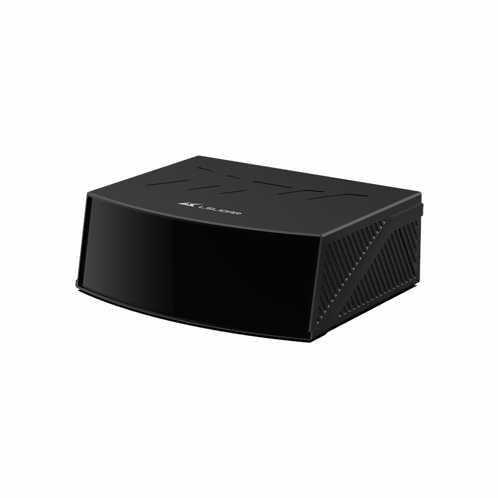
LS Lidar LS500W1 150m Ultra Wide Field of View 3D LiDAR
Get the best price for your setup
Contact our experts for the best possible price and configuration.
- Fast response
- Expert configuration advice
- No overpaying for features you do not need
Ultra-Wide 3D LiDAR for Construction and Autonomous Systems
The LS Lidar LS500W1 is a hybrid solid-state LiDAR developed for machines and vehicles that need a wide view of their surroundings. Its combination of a 120° horizontal and 73° vertical field of view allows a single sensor to monitor a large area, making it particularly useful for blind-spot detection, obstacle awareness and machine perception around construction equipment, autonomous vehicles and industrial systems.
Unlike a narrow single-point distance sensor, the LS500W1 produces a dense 3D point cloud. This allows a control system to determine not only how far away an object is, but also its position and approximate 3D profile. In practical field use, that makes it possible to detect people, vehicles, tyres, debris, loading material and surrounding structures within the sensor’s field of view.
Wide Field of View Helps Reduce Blind Areas
The LS500W1 covers 120° horizontally and 73° vertically. This unusually wide vertical coverage is especially useful on large machinery where obstacles may be located close to the vehicle, below the driver’s normal line of sight or around loading and working areas.
For loaders, mining trucks and other construction machinery, the wide viewing angle can help a machine perception system monitor areas that are difficult to cover with conventional cameras or narrower LiDAR sensors. The same characteristic is useful for autonomous platforms, mobile robots and industrial vehicles operating around people and equipment.
Up to 150 Metres Detection Range
The LS500W1 uses a 1550 nm Time of Flight laser system. Its specified detection range is 2 to 60 metres on targets with 10% reflectivity, with a maximum detection distance of up to 150 metres under suitable target and environmental conditions.
Reflectivity is important when comparing LiDAR range. Dark materials return less laser energy than bright or reflective surfaces, so the distance at which an object can be detected depends on the target itself as well as weather, installation angle and atmospheric conditions. For machine applications, the 60 m figure at 10% reflectivity provides a useful reference for more difficult targets, while the 150 m maximum indicates the longer-range capability available on stronger returns.
Dense Point Clouds for Object Detection and Volume Measurement
With a point generation rate of approximately 3.7 million points per second, the LS500W1 captures a large amount of spatial information within its field of view. This dense data can help software distinguish the shape and position of obstacles instead of relying on a single distance value.
One practical application is material handling. On a loader or similar machine, the 3D point cloud can be used to observe material in front of the vehicle and support functions such as pile or ore volume measurement. For autonomous and industrial applications, the same point cloud can be used for obstacle detection, environmental perception and navigation.
±2 cm Ranging Accuracy
The LS500W1 has a specified range accuracy of ±2 cm. In machine perception applications, this means the system receives consistent distance information with enough detail to locate objects and surfaces accurately within the LiDAR’s working area.
This accuracy is particularly valuable when the LiDAR is integrated with machine control, autonomous driving or monitoring software, where small errors in measured object position can affect path planning, collision avoidance or volume calculations.
Designed for Challenging Outdoor Environments
The LS500W1 is built for equipment that works outside and in industrial conditions. Its IP6K9K protection rating provides a high level of protection against dust and high-pressure water, while the specified operating temperature range extends from -40°C to +85°C.
The 1550 nm system is also intended to operate across different lighting conditions. LiDAR does not depend on ambient illumination in the same way as a conventional camera, which makes it suitable for day, night and low-light operation. Actual detection performance in rain, snow, fog or dust will still depend on the severity of the conditions and the installation.
Industrial Ethernet and Time Synchronisation
The LS500W1 communicates through Industrial Ethernet, making it suitable for integration with embedded computers, machine controllers and perception systems that need to process high-rate point cloud data. It supports GPS, PTP and gPTP time synchronisation, which is useful when LiDAR data needs to be aligned with cameras, GNSS, IMUs or other sensors.
This becomes especially important on autonomous vehicles, UAVs and mapping platforms where several sensors may be collecting data at the same time. Accurate timestamps allow software to combine those measurements correctly as the platform moves.
Suitable Applications
- Construction and mining machinery blind-spot detection
- Autonomous and driverless vehicles
- Industrial and logistics vehicles
- UAV and drone perception systems
- Security and perimeter monitoring
- Ports and automated material handling
- 3D mapping and machine perception
Integration into Machine and Mapping Systems
The LS500W1 operates from a 9–36 VDC input range and uses Industrial Ethernet for point cloud communication. The sensor measures approximately 270 × 160 × 80 mm and weighs up to 3 kg. These characteristics make it more suitable for vehicle, machinery and larger UAV integration than for lightweight handheld scanning.
For mapping and autonomous applications, the LiDAR can be combined with GNSS, IMU, cameras or other sensors to create a complete positioning and perception system. Its support for external timing makes this type of multi-sensor integration easier when accurate synchronisation is required.
Who Is the LS500W1 For?
The LS500W1 is primarily intended for engineers, integrators and machine manufacturers rather than users looking for a self-contained handheld scanner. It is a strong fit for construction equipment, mining machinery, autonomous vehicle projects, industrial automation, mapping platforms and other systems where the LiDAR becomes part of a larger hardware and software solution.
Buyers should consider the required field of view, target reflectivity, working distance, environmental conditions and data-processing requirements when selecting the sensor. Global GPS Systems can assist with product selection and integration questions when the LS500W1 is being combined with GNSS, positioning, mapping or machine-control equipment.
Valued customers:









Find RTK Networks
Search NTRIP providers and connect to reliable RTK correction services.
Description
The LS Lidar LS500W1 is a hybrid solid-state 3D LiDAR designed for construction machinery, autonomous systems, industrial vehicles, UAVs and other applications that need wide-area obstacle detection and dense point cloud data. Its 120° × 73° ultra-wide field of view helps cover large blind zones, while the 1550 nm laser provides a detection range of 2–60 m on 10% reflectivity targets and up to 150 m maximum. With ±2 cm ranging accuracy and approximately 3.7 million points per second, the LS500W1 can detect and profile people, vehicles, tyres, debris and surrounding structures in real time.
LS Lidar LS500W1 Highlights
| LiDAR type | Hybrid solid-state 3D LiDAR |
|---|---|
| Detection range | 2–60 m at 10% reflectivity, up to 150 m maximum |
| Range accuracy | ±2 cm |
| Field of view | 120° horizontal × 73° vertical |
| Point rate | Approx. 3.7–3.75 million points/sec |
| Laser wavelength | 1550 nm |
| Ingress protection | IP6K9K |
Datasheets & Manuals
Specifications
LSLiDAR CX1S3 Hybrid Solid-State LiDAR Specifications
Product Overview
| Product name | LSLiDAR CX1S3 |
|---|---|
| Product family | CX-S3 Series |
| Product type | Single-line hybrid solid-state LiDAR |
| Measurement principle | Time of Flight (ToF) |
| Scanning method | Mirror rotation with dedicated optical scanning design |
| Number of channels | 1 |
| Primary applications | Industrial detection, obstacle avoidance, 2D mapping, stockpile volume measurement, material-volume monitoring, high-speed vehicle profiling and large-area ranging |
| Typical industries | Industrial automation, mining, bulk-material handling, logistics, transportation, surveying, mapping and autonomous systems |
Standard / Long-Range CX1S3 Optical Specifications
| Laser wavelength | 905 nm |
|---|---|
| Laser safety class | Class 1, eye-safe |
| Detection method | ToF |
| Detection range | 150 m at 10% target reflectivity |
| Range precision / accuracy | ±3 cm |
| Horizontal field of view | 120° |
| Vertical field of view | Not applicable to the single-line CX1S3 architecture |
| Beam divergence | 3 × 3 mrad according to the CX1S3 V1.0.0 User Manual |
| Maximum scanning frequency | 150 Hz |
| Maximum data point rate | 150,000 points/second in single-echo mode |
Scanning Frequency and Angular Resolution
| Scanning Frequency | Horizontal Angular Resolution |
|---|---|
| 30 Hz | 0.024° |
| 60 Hz | 0.048° |
| 90 Hz | 0.072° |
| 120 Hz | 0.096° |
| 150 Hz | 0.12° |
Current CX1S3 Variant Comparison
| Specification | Near-Range | High-Precision | Long-Range |
|---|---|---|---|
| Laser wavelength | 905 nm | 905 nm | 905 nm |
| Channels | 1 | 1 | 1 |
| Detection principle | ToF | ToF | ToF |
| Detection range at 10% reflectivity | 50 m | 50 m | 150 m |
| Range precision | ±3 cm | ±1.5 cm | ±3 cm |
| Horizontal FOV | 120° | 120° | 120° |
| Horizontal resolution | 0.024° / 0.048° / 0.072° / 0.096° / 0.12° | 0.06° / 0.12° / 0.18° / 0.24° / 0.3° | 0.024° / 0.048° / 0.072° / 0.096° / 0.12° |
| Scanning frequency | 30 / 60 / 90 / 120 / 150 Hz | 30 / 60 / 90 / 120 / 150 Hz | 30 / 60 / 90 / 120 / 150 Hz |
| Maximum point rate | 150,000 pts/sec | 60,000 pts/sec | 150,000 pts/sec |
| Communication | Industrial Fast Ethernet | Industrial Fast Ethernet | Industrial Ethernet |
| Input voltage | 9–32 VDC | 9–32 VDC | 9–32 VDC |
| Dimensions | 110 × 101.4 × 45 mm | 110 × 100.4 × 45 mm in the high-precision manual; later brochure lists 110 × 101.4 × 45 mm | 110 × 101.4 × 45 mm |
High-Precision Variant
| Documented model | CX1S3G-R-2.0-50-A |
|---|---|
| Variant | CX1S3 High Precision |
| Detection range | 50 m at 10% reflectivity |
| Range precision | ±1.5 cm |
| Data point rate | 60,000 points/second in single-echo mode |
| Horizontal FOV | 120° |
| Scanning frequencies | 30 / 60 / 90 / 120 / 150 Hz |
| Horizontal angular resolution | 0.06° / 0.12° / 0.18° / 0.24° / 0.3° |
| Time source | GPS; gPTP synchronization is also documented in the high-precision manual |
Echo Modes
| Mode | Measurement Behavior |
|---|---|
| Single echo | Measures and outputs the most recent echo value |
| Dual echo | Measures and outputs the most recent and second-most-recent echo values |
Point Cloud Data
| Distance data | Included |
|---|---|
| Horizontal angle | Included |
| Intensity | Included |
| Laser ID | Included in parsed point data |
| Timestamp | Included |
| Cartesian coordinates | X, Y and Z coordinates can be calculated from the measured polar data |
| Horizontal angle data unit | 0.01° in the documented packet structure |
| Distance integer unit | Centimeters |
| Distance fractional resolution | 1/256 cm for the fractional distance byte |
| Timestamp resolution | Nanoseconds |
Communication Interface
| Primary communication interface | Industrial Ethernet |
|---|---|
| Standard CX1S3 manual interface | Gigabit Industrial Ethernet, 1000BASE-T |
| High-precision variant interface | Industrial Fast Ethernet |
| Network transport | UDP/IP |
| Supported network modes | Unicast, broadcast and multicast |
| Data byte order | Big-endian for documented packet fields |
UDP Protocols
| Protocol | Function |
|---|---|
| MSOP | Main point-cloud measurement data output |
| DIFOP | Device information, Ethernet configuration, motor / scanner status, operating status and fault-diagnosis output |
| UCWP | User configuration write protocol for configurable LiDAR parameters |
Network Defaults
| Device | Default IP | UDP Device Packet Port | UDP Data Packet Port |
|---|---|---|---|
| CX1S3 LiDAR | 192.168.1.200 | 2368 | 2369 |
| Host computer | 192.168.1.102 | 2369 | 2368 |
Time Synchronization
| GPS synchronization | Supported |
|---|---|
| gPTP synchronization | Supported |
| Internal timing | Supported when no external synchronization source is connected |
| GPS PPS | Supported |
| GPS serial message | NMEA $GPRMC |
| GPS serial baud rate | 9600 bps |
| GPS serial configuration | 8 data bits, no parity, 1 stop bit |
| GPS interface levels | TTL and RS-232 versions documented |
| RS-232 PPS input level | 3.0–15.0 V |
| Recommended PPS pulse width | Greater than 1 ms |
| UTC time source | Extracted from GPS $GPRMC data when GPS synchronization is used |
| INS integration | Timestamped point-cloud data can be matched with pitch, roll, yaw, latitude, longitude and height from a compatible GPS / inertial system |
Electrical Specifications
| Input voltage | 9–32 VDC |
|---|---|
| Recommended supply voltage | 24 VDC |
| 9 V / 32 V supply note | Manufacturer manual identifies 9 V and 32 V as short-term extreme limits rather than preferred continuous operating voltages |
| Recommended supply current capability | ≥2 A to accommodate startup current |
| Maximum recommended ripple | <120 mVp-p |
| Recommended supply voltage accuracy | <5% |
| Power consumption | Not specified as a dedicated CX1S3 value in the reviewed CX1S3 model specification tables |
| Series-level power note | Some CX-series sales material quotes power consumption as low as 13.5 W; this figure should not be treated as a confirmed CX1S3 model value without checking the supplied hardware revision |
Connector and Wiring
| Main LiDAR connector | 8-pin connector; high-precision manual identifies interface model SZCNT12-M12-Z08A118A |
|---|---|
| Power input pin | VIN / VCC |
| Ethernet transmit | TX+ / TX− pair |
| Ethernet receive | RX+ / RX− pair |
| GPS PPS | Dedicated synchronization input |
| GPS receive | Dedicated GPS_REC input |
| Ground | Power and GPS signal ground |
Adapter Cable Interfaces
| LiDAR connector | Aviation-style LiDAR connector |
|---|---|
| Power connector | 5.5 × 2.1 mm DC connector in the documented adapter cable |
| Ethernet connector | Standard RJ45 |
| Timing synchronization connector | DB-9 |
| Timing signals | GPS PPS and serial GPS receive |
| Optional interface box | Available for applicable variants and testing / integration workflows |
| Interface box connections | DC input, indicator, RJ45 Ethernet and GPS synchronization interface |
Environmental Specifications
| Operating temperature | -40°C to +85°C |
|---|---|
| Storage temperature | -40°C to +105°C |
| Ingress protection – CX1S3 V1.0.0 manual / English datasheet | IP6K9K |
| Ingress protection – later CX1S3 variant brochure | IP67 |
| Vibration | 5–2000 Hz, 3 g RMS |
| Shock | 500 m/s² for 11 ms |
| Approximate shock acceleration | Approximately 51 g |
| Environmental-rating note | Published ingress-protection ratings differ between documentation revisions; confirm the rating of the exact CX1S3 hardware variant supplied |
Physical Specifications
| Length | 110 mm |
|---|---|
| Width | 101.4 mm for the standard / long-range model |
| Height | 45 mm |
| Overall dimensions – standard / long-range | 110 × 101.4 × 45 mm |
| Weight – standard documentation | 635 g |
| Later variant brochure weight | <1 kg depending on CX1S3 variant / production revision |
| Mounting holes | 4 |
| Positioning holes | 2 |
| Recommended mounting screws | 4 × M4 × 10 mm hexagon socket-head cap screws |
| Mounting washers | Spring and flat washers documented |
| Documented tightening torque | 5 N·m |
| Optical center | Documented as the coordinate origin used by the manufacturer point-cloud display software |
Windows Software
| Manufacturer software | CX1S3 Windows Client / point-cloud display software |
|---|---|
| Operating system | Windows x64 |
| Installation | Manufacturer documentation describes the client as a portable application that does not require a conventional installation |
| Live point-cloud display | Supported |
| Offline point-cloud playback | Supported |
| Point-data table | Displays Point ID, XYZ coordinates, azimuth, distance, intensity, laser ID and timestamp |
| Parameter configuration | Supported |
| Packet discovery / diagnostics | Wireshark can be used to capture ARP and network packets |
| Packet capture library | WinPcap is required by the documented Windows Client workflow |
Windows Host Computer Requirements
| Component | Manufacturer Requirement / Recommendation |
|---|---|
| Operating system | 64-bit Windows |
| Processor | Intel Core i5 or higher |
| Graphics card | NVIDIA GeForce GTX 750 or higher recommended for best point-cloud display performance |
| Graphics API | OpenGL 2.0 or higher required for normal point-cloud display |
| Ethernet | Compatible Ethernet adapter required |
Linux and ROS Support
| Linux support | Supported through the LSLiDAR ROS driver |
|---|---|
| ROS1 driver | Official LSLiDAR ROS1 driver includes CX1S3 support |
| Documented ROS environment | Ubuntu 16.04 with ROS Kinetic and Ubuntu 18.04 with ROS Melodic are documented by LSLiDAR's ROS1 driver repository |
| ROS visualization | RViz-compatible workflow documented |
| Network diagnostics | tcpdump can be used to confirm packet reception under Linux |
Configurable Functions
| Scanning frequency | Configurable among supported frequency settings |
|---|---|
| Network configuration | Configurable |
| Destination IP | Configurable |
| Destination port | Configurable within supported protocol requirements |
| Echo mode | Single and dual echo supported |
| Clock source | GPS, gPTP or internal timing according to configuration |
| Standby mode | Supported; documented standby mode disables laser emission |
| Phase lock | Configurable in the documented protocol |
Anti-Interference and Reliability
| Strong-light resistance | Designed for reliable operation under strong sunlight |
|---|---|
| LiDAR-to-LiDAR interference resistance | LSLiDAR CX-series technology uses laser coding to reduce interference from other LiDAR systems |
| Self-diagnostics | Device status and fault-diagnosis information is available through the DIFOP device-data protocol |
| Industrial design | Designed for continuous industrial detection, mapping and obstacle-avoidance applications |
Laser Safety
| Laser class | Class 1 |
|---|---|
| Eye-safe classification | Yes, when operated according to manufacturer instructions |
| Laser safety reference | IEC 60825 Class 1 is referenced in LSLiDAR product documentation |
| Housing requirement | Manufacturer instructs users not to operate the LiDAR with a damaged or unsecured housing |
| User disassembly | Not permitted by the manufacturer |
Typical Applications
| Application | Typical Function |
|---|---|
| Stockpile volume measurement | High-speed profile acquisition for calculating bulk-material volume |
| Coal stockpile monitoring | Surface-profile and volume measurement |
| Grain storage | Material profile and volume monitoring |
| Vehicle profiling | High-frequency scanning of moving vehicle outlines |
| Over-height / overload monitoring | Fast profile measurement in intelligent transportation applications |
| Industrial obstacle avoidance | Long-range 2D obstacle detection |
| 2D mapping | Distance and reflectivity acquisition across a 120° horizontal field |
| Autonomous equipment | Environmental detection and collision-avoidance input |
Documented Accessories and Integration Items
| Item | Quantity | Notes |
|---|---|---|
| CX1S3 LiDAR | 1 | Exact near-range, high-precision or long-range variant depends on configuration |
| Power / Ethernet adapter cable | Configuration-dependent | Documented as the standard connection method in the CX1S3 manual |
| Windows Client software | 1 software package | Manufacturer manual documents delivery on USB flash storage or availability from LSLiDAR support |
| WinPcap package | 1 software package | Documented dependency for the Windows Client |
| Interface box | Optional | Provides convenient DC, Ethernet and GPS synchronization interfaces on applicable configurations |
| Mounting hardware | Configuration-dependent | LiDAR design uses four M4 × 10 mm fixing screws plus spring and flat washers |
Documentation and Revision Notes
| Standard User Manual researched | CX1S3 User Manual V1.0.0, December 2023 |
|---|---|
| High-Precision User Manual researched | CX1S3 High Precision User Manual V1.0.1, October 2024 |
| Official model-specific detection range | 150 m at 10% reflectivity for the standard / long-range CX1S3 |
| Series-level seller information | The Global GPS Systems page also contains specifications for other CX-family models such as 200 m detection range and 1.53 million points/second; these are not the model-specific CX1S3 values |
| Model-specific CX1S3 point rate | 150,000 points/second for the standard / long-range CX1S3 |
| Model-specific CX1S3 range precision | ±3 cm standard / long-range; ±1.5 cm high-precision variant |
| Ingress-rating documentation difference | Earlier English datasheet and CX1S3 manual specify IP6K9K, while a later official CX1S3-series brochure specifies IP67 for the near-range, high-precision and long-range versions; verify the exact production revision supplied |
Specifications and package contents may vary by configuration, region or manufacturer update. Always check the current configuration before ordering.
Additional information
| Solution | Standalone Solution, Stockpile Volume Measurement Solution |
|---|
Reviews (0)
Only logged in customers who have purchased this product may leave a review.
FAQ
LS LiDAR CX1S3 FAQ
CX1S3 LiDAR & Applications
What is the LS LiDAR CX1S3?
The LS LiDAR CX1S3 is a compact single-line hybrid solid-state LiDAR sensor designed for high-speed 2D environmental scanning, distance measurement, object detection and obstacle avoidance. It uses Time of Flight technology and provides a 120-degree horizontal field of view with detection distances up to 150 metres on targets with 10% reflectivity.
Is the LS LiDAR CX1S3 a 2D or 3D LiDAR?
The CX1S3 is a single-channel 2D LiDAR. It scans across a 120-degree horizontal field of view but does not have a vertical scanning field like a multi-channel 3D LiDAR. A 3D model can be created when the sensor is combined with controlled motion, positioning information or another mechanism that provides the additional spatial dimension.
What is the CX1S3 designed for?
The CX1S3 is designed for industrial applications that require fast and accurate distance and reflectivity measurements across a wide horizontal area. Typical uses include obstacle avoidance, industrial automation, autonomous equipment, vehicle perception, 2D mapping, safety monitoring and integration into specialised measurement systems.
Can the CX1S3 be used for obstacle detection and collision avoidance?
Yes. Obstacle detection and avoidance are core applications of the CX1S3. Its fast scanning rate, 120-degree field of view and long detection range allow compatible control software to monitor objects and obstacles in front of vehicles, machines or automated equipment.
Can the CX1S3 be used for stockpile volume measurement?
Yes, the CX1S3 can be integrated into a stockpile volume measurement solution. Because it is a single-line scanner, the sensor normally needs to be combined with movement, positioning and suitable processing software to build the 3D geometry required for volume calculations. It should therefore be considered a sensing component within the complete measurement system rather than a standalone volume-calculation instrument.
What is the difference between the CX1S3 and a multi-channel 3D LiDAR?
The CX1S3 uses one laser channel and scans horizontally, producing a high-resolution 2D profile. Multi-channel LiDAR sensors measure multiple vertical angles simultaneously and can generate a 3D point cloud directly. The CX1S3 is well suited to applications where detailed horizontal scanning, rapid updates, compact dimensions and long-range detection are more important than a large vertical field of view.
Range, Accuracy & Scanning Performance
What is the detection range of the LS LiDAR CX1S3?
The CX1S3 has a specified detection range of up to 150 metres on a target with 10% reflectivity. Actual usable range can vary with target reflectivity, atmospheric conditions, target angle, contamination of the optical window and environmental lighting.
How accurate is the LS LiDAR CX1S3?
The CX1S3 has a specified ranging accuracy of approximately ±3 cm under suitable operating conditions. System-level accuracy can also depend on installation, calibration, synchronization, target characteristics and any positioning equipment used with the LiDAR.
What is the field of view of the CX1S3?
The CX1S3 provides a 120-degree horizontal field of view. Because it is a single-line LiDAR, it does not have a multi-layer vertical field of view. It scans a horizontal profile across the monitored area.
What scanning frequencies does the CX1S3 support?
The CX1S3 supports scanning frequencies of 30, 60, 90, 120 and 150 Hz. This allows the operating mode to be selected according to whether the application prioritises finer angular resolution or a faster update rate.
What is the angular resolution of the CX1S3?
The CX1S3 supports horizontal angular resolutions of approximately 0.024°, 0.048°, 0.072°, 0.096° and 0.12°. The available resolution is related to the selected scanning frequency, with finer angular spacing available at lower scan rates.
How many measurement points does the CX1S3 generate?
The CX1S3 has a specified data-point generation rate of approximately 150,000 points per second. This enables a dense 2D representation of objects and surfaces across its horizontal scanning area.
Does the CX1S3 measure reflectivity as well as distance?
Yes. The CX1S3 provides distance and reflectivity information for detected targets. Reflectivity information can help downstream software distinguish changes in surface response and can be useful in mapping, detection and industrial perception applications.
Laser, Communication & System Integration
How does the CX1S3 measure distance?
The CX1S3 uses Time of Flight technology. The LiDAR emits a laser pulse and measures the time required for the reflected light to return from a target. The travel time is then used to calculate the distance between the sensor and the detected surface.
What laser wavelength does the CX1S3 use?
The CX1S3 uses a 905 nm near-infrared laser. This wavelength is widely used in automotive and industrial Time of Flight LiDAR systems.
Is the LS LiDAR CX1S3 eye-safe?
Yes. The CX1S3 is specified as a Class 1 laser product. It should nevertheless be installed, operated and maintained according to the manufacturer's laser-safety instructions, and the optical system should not be modified or disassembled.
How does the CX1S3 connect to a computer or controller?
The CX1S3 uses Gigabit Industrial Ethernet with a 1000BASE-T connection for transferring LiDAR measurements and communicating with an external computer or control system. This high-speed connection supports the sensor's real-time measurement output.
Does the CX1S3 support time synchronization?
Yes. The CX1S3 supports GPS-based time synchronization and gPTP synchronization. Accurate timing is particularly important when LiDAR data is combined with GNSS, an IMU, cameras or other sensors on a moving platform.
Can the CX1S3 be combined with GNSS and an IMU?
Yes. The CX1S3 can be incorporated into a system that combines LiDAR measurements with GNSS and inertial data. With appropriate synchronization, calibration and processing software, pose information such as position, roll, pitch and heading can be associated with the LiDAR measurements for mobile mapping and other georeferenced applications.
Power, Durability & Installation
What power supply does the CX1S3 require?
The CX1S3 supports an input voltage of approximately 9 to 32 VDC. This wide input range makes the sensor suitable for integration into vehicles, industrial machines, autonomous platforms and fixed monitoring systems with compatible power supplies.
Is the CX1S3 waterproof and dustproof?
The CX1S3 has an IP6K9K environmental protection rating. This provides a high level of protection against dust and high-pressure, high-temperature water jets, making it suitable for demanding outdoor, vehicle and industrial installations when installed according to the manufacturer's requirements.
What temperature range can the CX1S3 operate in?
The specified operating temperature range of the CX1S3 is approximately -40°C to +85°C. Its specified storage temperature range is approximately -40°C to +105°C, supporting integration into equipment intended for demanding environmental conditions.
Is the CX1S3 resistant to shock and vibration?
Yes. The CX1S3 is designed for industrial and mobile installations. Manufacturer specifications include vibration testing from 5 to 2000 Hz at 3G RMS and shock testing of approximately 500 m/s² for 11 ms.
How large and heavy is the LS LiDAR CX1S3?
The CX1S3 measures approximately 110 × 100.4 × 45 mm and weighs approximately 635 g. Its compact, low-profile housing makes it suitable for integration into machines, vehicles and other systems where installation space is limited.
How is the CX1S3 mounted?
The CX1S3 has four mounting holes and two positioning holes on the bottom of the housing. Manufacturer documentation specifies M4 × 10 mounting screws for securing the sensor. The unit should be mounted rigidly with an unobstructed optical field of view, and applications involving mapping or measurement should accurately determine the sensor's position and orientation relative to the host platform.
 GPS & GNSS
 Total Stations
 Data collectors
 Software
 Correction services
 Machine control
 External radio
 Marine
 Accessories
Reviews
There are no reviews yet