

 GPS & GNSS
 Lidar scanning
 Total Station
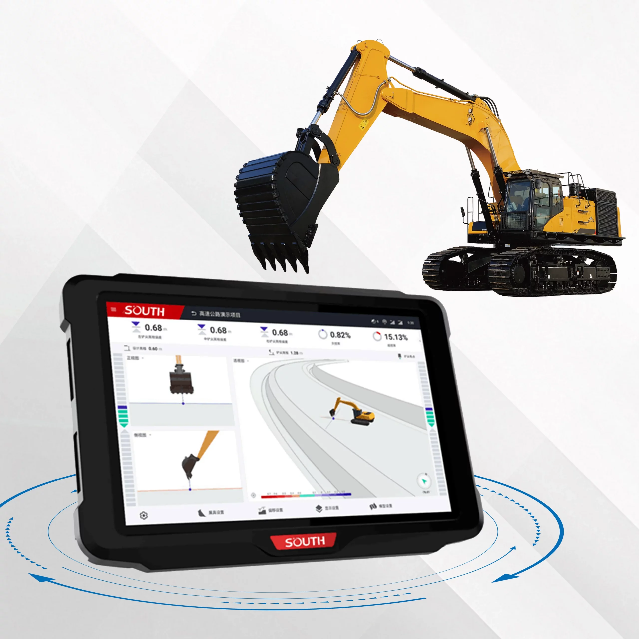
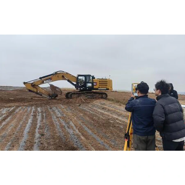

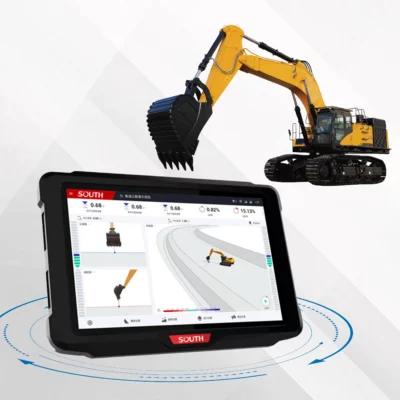
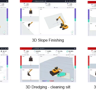
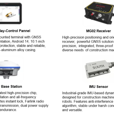
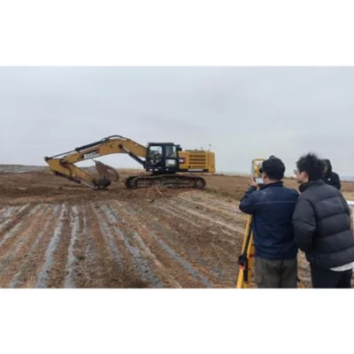
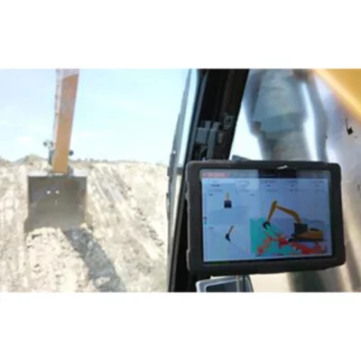
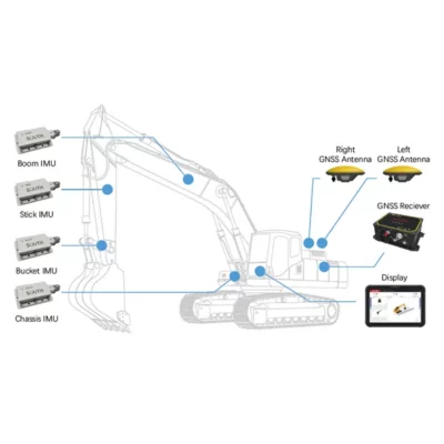
SOUTH EGS01 Intelligent 3D Excavator Guidance System
Get the best price for your setup
Contact our experts for the best possible price and configuration.
- Fast response
- Expert configuration advice
- No overpaying for features you do not need
The SOUTH EGS01 Intelligent 3D Excavator Guidance System gives operators real-time information about the bucket tip’s position in relation to the required excavation surface. By combining high-precision GNSS positioning, four IMU sensors and engineering design data, the system helps operators excavate, grade and shape slopes with horizontal and elevation guidance accuracy of up to ±3 cm.
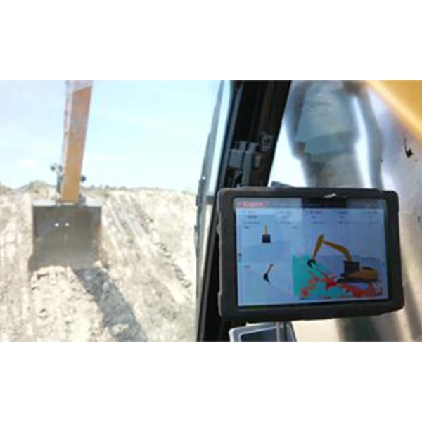
The in-cab display shows whether the bucket is above, below or correctly aligned with the target surface. This reduces reliance on repeated grade checks and helps prevent over-excavation or under-excavation. It is suitable for road construction, house and commercial foundations, utility trenches, municipal works, dredging, mining, pit excavation and general earthmoving projects.
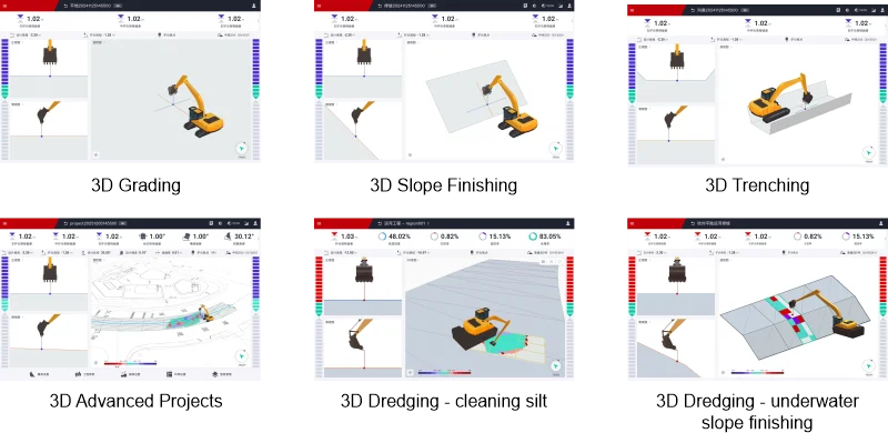
Magnetic sensor mounting allows the system to be installed without welding, while guided calibration supports different excavators, boom configurations and attachments. Depending on the selected software version, operators can work with basic sloping, trenching and grading models or import detailed DXF and LandXML designs for model-based excavation.
SOUTH EGS01 Excavator Guidance System Highlights
| Guidance accuracy | Up to ±3 cm horizontally and vertically |
|---|---|
| Positioning technology | High-precision GNSS with four IMU sensors |
| Core applications | Sloping, trenching, grading and design-surface excavation |
| Design file support | DXF and LandXML in the Premium version |
| Satellite constellations | GPS, GLONASS, Galileo and BeiDou |
| Correction compatibility | CORS networks and compatible GNSS base stations |
| Installation | Magnetic mounting without welding |
| Machine compatibility | Supports multiple boom types and excavator attachments |
Valued customers:







Find RTK Networks
Search NTRIP providers and connect to reliable RTK correction services.
Description
Real-time 3D guidance for excavator operators
The SOUTH EGS01 Intelligent 3D Excavator Guidance System is designed to help excavator operators complete earthmoving work directly from digital design information. The system continuously calculates the excavator’s position and movement, then shows the bucket tip in relation to the required elevation, slope or 3D design surface on an in-cab display.
Instead of relying only on stakes, string lines or frequent measurements from a surveyor, the operator receives immediate guidance while digging. The display indicates how far the bucket is from the target surface, helping the operator decide where additional material must be removed and where the correct level has already been reached.
GNSS and IMU sensor fusion
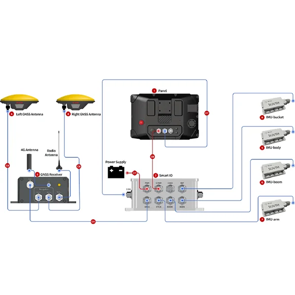
The EGS01 combines high-precision GNSS positioning with four IMU sensors mounted on the excavator. GNSS determines the machine’s position within the project coordinate system, while the IMU sensors measure the movement and orientation of the boom, stick, bucket and machine body.
By combining these measurements with the excavator’s calibrated dimensions, the guidance software calculates the position of the bucket tip in real time. SOUTH specifies horizontal and elevation guidance accuracy of up to ±3 cm under suitable operating and correction conditions.
In practical fieldwork, this allows operators to work closer to the finished design level without repeatedly leaving the cab or waiting for a separate grade check. The final construction tolerance will also depend on the GNSS correction quality, machine condition, calibration, bucket wear, operating technique and site conditions.
Reduce over-excavation and unnecessary rework
Excavating beyond the required design level can lead to additional material, compaction and labour costs. Stopping too high may require another machine pass or further manual checks. The EGS01 provides continuous feedback so the operator can approach the required surface more consistently.
For trenching, the system can help maintain the specified depth, direction and slope along the excavation. During grading or foundation preparation, the operator can monitor the bucket relative to the required level across the working area. For slope construction, the guidance display helps the operator follow the intended inclination without depending on visual estimation alone.
Standard sloping, trenching and grading functions
The Standard 3D version includes common earthwork functions for sloping, trenching and grading. Operators can enter the required parameters and use the live bucket guidance to construct the selected profile.
These functions are suitable for straightforward projects where the required geometry can be defined directly in the system. Typical examples include drainage trenches, pipeline excavations, foundation pads, simple road sections, embankments, ditches and small-scale grading work.
Advanced model-based excavation
The Premium version supports the import of DXF and LandXML design data. This allows contractors to use detailed surface and line models prepared by surveyors, civil engineers or design teams.
Once a design has been loaded, the operator can work directly against the model. The system can display elevation deviation, horizontal distance deviation and cross-slope angle deviation. Layers and design objects can be shown or hidden, selected for vertical or horizontal guidance and adjusted using offsets when required.
This model-based workflow is valuable on projects containing changing levels, curved alignments or complex surfaces that would be difficult to reproduce with basic entered slopes. Roads, commercial foundations, large drainage works, dredging and infrastructure projects can therefore be completed with closer alignment between the excavator’s work and the engineering design.
Support for 2D to 3D project workflows
Projects that still use conventional 2D drawings can be prepared for machine guidance by converting centreline and design information into a usable 3D model. This allows contractors to introduce digital guidance without requiring every original project file to have been created as a complete 3D surface.
This approach is especially useful for roads, slopes and dredging work, where alignments, elevations and cross-sections can be developed into a model that the excavator operator can follow in the field.
Fast installation without welding
The EGS01 uses magnetic mounting for its machine sensors, avoiding the need to weld brackets permanently onto the excavator. SOUTH states that installation and calibration can be completed in under one hour when carried out by an experienced installer under suitable conditions.
Guided calibration records the excavator’s dimensions, sensor positions and attachment geometry. Machine profiles can be exported and imported, allowing saved configurations to be reused. This is useful for contractors who operate several excavators or regularly change between compatible attachments.
Compatible with different machines and attachments
The system supports a range of excavator arrangements, including mono boom, dual boom and swing boom machines. Compatible attachment configurations include standard buckets, blade buckets, tilt buckets, breakers, triangle buckets and U-shaped buckets. It also supports tilt, rotor and tiltrotator arrangements where the appropriate configuration is available.
This flexibility makes the EGS01 suitable for general contractors, specialist excavation companies, road builders, utility contractors, dredging teams and mining operators using different machine types across multiple projects.
Multi-constellation GNSS positioning
The guidance system can use signals from GPS, GLONASS, Galileo and BeiDou satellites. Access to several satellite constellations improves the number and geometry of available satellites, which can help maintain stable positioning across open construction sites.
Centimetre-level guidance requires suitable differential corrections. The EGS01 supports compatible CORS and network RTK services as well as compatible GNSS base-station corrections. The best correction method depends on local network coverage, project location, required working range and the contractor’s existing survey equipment.
Coordinate systems and project compatibility
The software includes more than 2,000 coordinate-system templates, including commonly used systems such as WGS 84 and UTM. It also supports the import of relevant calibration and coordinate files, including DC, CAL and LandXML formats.
Using the correct project coordinate system is essential because the excavator guidance must align with the survey control and design data used on the construction site. Surveyors or site engineers can prepare the required coordinate information before transferring it to the machine.
Cloud-based project collaboration
Cloud functionality allows design models and coordinate-system information to be delivered remotely to supported machines. Updated files can be shared across several excavators, helping the project team keep machines working from the same current design.
This can reduce manual file transfer and improve coordination between the office, survey team and operators. When an engineering model changes, the revised information can be prepared and distributed without rebuilding the complete machine configuration from the beginning.
Applications across construction and earthmoving
The SOUTH EGS01 can be used for highway and road construction, municipal infrastructure, residential and commercial foundations, long-distance pipeline trenches, drainage work, grading, slope construction, dredging, mining and pit excavation.
Road contractors can use the system to prepare formation levels, drainage features and embankment slopes. Utility contractors can follow the intended depth and grade of pipe or cable trenches. Foundation teams can excavate pads and footings closer to the required design elevation, while mining and quarry operators can use digital guidance for pit, bench and material-removal work.
Designed for operators, surveyors and project teams
The main user is the excavator operator, who receives continuous visual guidance in the cab. Surveyors and site engineers remain important for establishing control, checking the coordinate system, preparing design models and verifying the completed work.
For contractors, the system can reduce interruptions caused by routine level checks and help experienced operators transfer the engineering design into the ground more consistently. It does not replace project control or quality assurance, but it can make the excavation workflow more direct and less dependent on repeated manual marking.
Configuration and support from Global GPS Systems
Global GPS Systems can help configure the SOUTH EGS01 for the machine, attachment, GNSS correction source and project workflow in which it will be used. Correct installation, calibration and design-data preparation are essential for reliable guidance results.
Support can also cover coordinate-system setup, base-station or CORS connectivity, machine profiles and the transfer of DXF or LandXML project data. This gives contractors a complete guidance workflow rather than a collection of separate machine sensors and positioning components.
Datasheets & Manuals
Specifications
SOUTH EGS01 Intelligent 3D Excavator Guidance System Specifications
Product Overview
| Product Name | SOUTH EGS01 Intelligent 3D Excavator Guidance System |
|---|---|
| Model | EGS01 |
| Product Type | GNSS and IMU-based 3D machine guidance system for excavators |
| Primary Function | Provides real-time excavation guidance by comparing the excavator bucket position with construction design surfaces and models |
| Guidance Method | Real-time 3D visual guidance |
| Positioning Technology | High-precision GNSS positioning combined with multiple IMU tilt and posture sensors |
| Design Data Integration | Integrates surveying data, engineering design data, coordinate systems and 3D terrain models |
| Operator Interface | In-cab display presenting the bucket position, design surface and excavation deviations in real time |
Guidance Accuracy
| Horizontal Guidance Accuracy | Up to ±3 cm |
|---|---|
| Elevation Guidance Accuracy | Up to ±3 cm |
| Guided Reference Point | Excavator bucket tip or selected attachment reference point |
| Real-time Deviation Feedback | Elevation deviation, horizontal distance deviation and cross-slope angle deviation |
| Machine Posture Tracking | Continuous tracking of the excavator’s spatial position, boom geometry, attachment orientation and working posture |
| Excavation Control | Helps prevent over-excavation and under-excavation by displaying the bucket position relative to the design surface |
Positioning and Sensor System
| GNSS Receiver | High-precision GNSS receiver |
|---|---|
| GNSS Antennas | Dual-antenna configuration |
| IMU Sensors | Four IMU sensors for machine and attachment posture measurement |
| Sensor Fusion | GNSS positioning and IMU tilt-sensor fusion with machine-guidance algorithms |
| Supported Satellite Systems | GPS, GLONASS, Galileo and BeiDou |
| Differential Correction Sources | CORS network corrections and compatible GNSS base-station corrections |
| Supported Correction Services | SmartNet CORS, Trimble base stations and Leica base stations |
| Heading Determination | Dual-GNSS-antenna heading and orientation determination |
3D Standard Version Functions
| Sloping Mode | Supports guided construction of predefined slopes |
|---|---|
| Trenching Mode | Supports excavation guidance for trenches, channels and utility works |
| Grading Mode | Supports elevation and surface guidance for grading operations |
| Model Parameter Setup | Operators can define project geometry and guidance parameters directly within the system |
| Continuous Bucket Feedback | Displays the bucket position continuously relative to the configured design surface |
| Earthwork Quality Control | Assists operators in achieving specified slopes, depths, grades and elevations without repeated manual checks |
3D Premium Version Functions
| 3D Design Model Import | Supported |
|---|---|
| Supported Design Formats | DXF and LandXML |
| Complex Surface Models | Supports imported complex 3D surface models |
| Line Models | Supports imported line-based design models |
| Model-based Guidance | Continuous real-time excavation guidance directly against an imported design model |
| Layer Control | Imported model layers and objects can be shown or hidden |
| Object Selection | Individual design objects can be enabled or disabled for elevation or horizontal guidance |
| Design Offsets | Offsets can be applied to imported objects after model import |
| 2D-to-3D Conversion | Cloud-based conversion of compatible 2D drawings into 3D guidance models |
| Centerline-based Model Support | Suitable for roads, slopes, channels, dredging works and other centerline-based projects |
Coordinate Systems and Project Data
| Preloaded Coordinate-System Templates | More than 2,000 industry-standard templates |
|---|---|
| Global Coordinate-System Support | Supported |
| Example Coordinate Systems | WGS 84, UTM and other regional or project coordinate systems |
| Coordinate-System File Import | Supported |
| Supported Coordinate Files | .dc, .cal and LandXML |
| Survey Data Integration | Supports project positioning and guidance based on survey control and engineering design data |
| Multi-machine Project Synchronization | Supported through cloud-based project-data distribution |
Cloud Connectivity and Collaboration
| Cloud Collaboration | Supported |
|---|---|
| Remote Design-File Delivery | 3D design files can be delivered remotely to connected machines |
| Remote Coordinate-System Delivery | Coordinate-system configurations can be distributed remotely |
| Project Updates | Updated designs and project configurations can be synchronized with machines in the field |
| Fleet Coordination | Supports consistent project data across multiple excavators working on the same site |
| 2D Drawing Conversion | Cloud tools support one-click conversion of compatible 2D project drawings into 3D models |
Machine Compatibility
| Machine Type | Hydraulic excavators |
|---|---|
| Mono Boom | Supported |
| Dual Boom | Supported |
| Swing Boom | Supported |
| Tiltrotator | Supported |
| Tilt Function | Supported |
| Rotor Function | Supported |
| Machine Profiles | Calibration profiles can be exported and imported for compatible machines and attachments |
| Attachment Calibration | Guided calibration supports different excavator attachments and working geometries |
Attachment Compatibility
| Standard Bucket | Supported |
|---|---|
| Blade | Supported |
| Tilt Bucket | Supported |
| Breaker | Supported |
| Triangle Bucket | Supported |
| U-shaped Bucket | Supported |
| Additional Attachments | May be supported through attachment-specific calibration and profile configuration |
Installation and Calibration
| Typical Installation and Calibration Time | Under one hour |
|---|---|
| Sensor Mounting Method | Magnetic mounting |
| Welding Required | No |
| Calibration Workflow | Guided machine and attachment calibration |
| Calibration Profile Export | Supported |
| Calibration Profile Import | One-click profile import supported |
| Machine Reconfiguration | Stored profiles simplify changing between calibrated machines or attachments |
System Benefits and Functions
| Survey Stake Reduction | Reduces reliance on repeated staking, grade checking and manual surveying during excavation |
|---|---|
| Rework Reduction | Real-time design comparison helps reduce excavation errors and corrective work |
| Material Control | Helps reduce unnecessary removal, replacement and movement of material |
| Operational Efficiency | Provides continuous guidance so operators can work toward the specified grade, depth or surface without stopping for frequent checks |
| Construction Quality | Supports closer alignment between completed excavation and the engineering design |
| Safety Assistance | Design and project information can help operators maintain awareness of underground utilities, boundaries and other mapped obstacles |
| Fuel and Time Efficiency | Reduced rework and unnecessary machine movement can shorten operating cycles and lower fuel use |
Applications
| Highway Construction | Road formation, grading, slopes, drainage and earthworks |
|---|---|
| Municipal Works | Urban earthworks, utilities, drainage and public-infrastructure construction |
| House Foundations | Foundation excavation, level control and building-pad preparation |
| Long-distance Pipe Trenches | Depth, grade and alignment guidance for pipeline and utility trenching |
| Dredging | Model-guided excavation and profile control for dredging operations |
| Mining | Excavation, benching, grading and material-removal operations |
| Sloping | Construction and trimming of specified slopes |
| Trenching | Excavation of utility, drainage and infrastructure trenches |
| Grading | Surface preparation and elevation control |
| Pit Excavation | Depth and boundary guidance for pits, foundations and bulk excavation |
| Commercial Construction | Foundation work, site preparation and design-surface excavation |
| Infrastructure Development | Precision earthworks for roads, rail, utilities, drainage and civil-engineering projects |
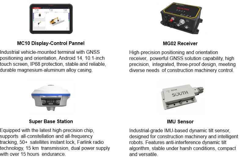
System Components
| Item | Quantity | Notes |
|---|---|---|
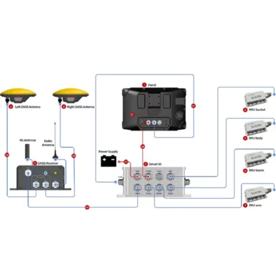
| IMU Sensor | 4 | Measures the orientation and movement of the excavator’s structural components and attachment |
| GNSS Antenna | 2 | Dual-antenna positioning and heading configuration |
| In-cab Display | 1 | Provides real-time 3D guidance, design visualization and deviation information |
| GNSS Receiver | 1 | Processes satellite positioning and differential correction data |
| Mounting and Connection Hardware | Configuration dependent | Hardware selection may vary according to the excavator, boom arrangement and attachment type |
| Machine-Guidance Software | 1 system licence | Standard or Premium functionality depends on the selected configuration and licence |
Version Comparison
| Function | 3D Standard Version | 3D Premium Version |
|---|---|---|
| Sloping Guidance | Supported | Supported |
| Trenching Guidance | Supported | Supported |
| Grading Guidance | Supported | Supported |
| 3D Design Model Import | Not specified | Supported |
| DXF Import | Not specified | Supported |
| LandXML Import | Not specified | Supported |
| Complex Surface and Line Models | Not specified | Supported |
| Layer and Object Controls | Not specified | Supported |
| Elevation and Horizontal Object Selection | Not specified | Supported |
| Object Offsets | Not specified | Supported |
| 2D-to-3D Cloud Conversion | Not specified | Supported |
Specifications and package contents may vary by configuration, region or manufacturer update. Always check the current configuration before ordering.
Reviews (0)
Only logged in customers who have purchased this product may leave a review.
FAQ
SOUTH EGS01 Intelligent 3D Excavator Guidance System FAQ
System Overview and Applications
What is the SOUTH EGS01 Intelligent 3D Excavator Guidance System?
The SOUTH EGS01 is a machine guidance system that uses high-precision GNSS positioning, IMU tilt sensors, engineering design data and onboard software to guide an excavator operator in real time. It displays the bucket’s position relative to the required design surface, line or elevation.
Who is the EGS01 designed for?
The system is designed for excavator operators, earthworks contractors, civil engineering companies, road builders, utility contractors, mining operations, dredging teams, surveyors and construction project managers who need accurate excavation and grading.
What types of projects can use the EGS01?
Typical applications include highway construction, municipal works, house and commercial foundations, pipe trenches, dredging, mining, slope construction, grading, trenching and pit excavation.
How does the EGS01 guide an excavator operator?
The system continuously calculates the position and orientation of the excavator and bucket. The in-cab display then shows real-time differences between the bucket and the required design, including elevation, horizontal distance and cross-slope deviations where supported.
What accuracy can the EGS01 achieve?
The manufacturer specifies bucket-tip horizontal and elevation accuracy of up to ±3 centimetres. Actual project accuracy can depend on GNSS correction quality, calibration, machine condition, satellite visibility, design data and operating conditions.
Can the EGS01 reduce the need for manual surveying?
Yes. Real-time guidance can reduce repeated grade checking, staking and survey support during excavation. Survey control and verification may still be required according to the project specification and quality-control procedure.
Guidance Functions and Design Models
What functions are included in the EGS01 3D Standard Version?
The 3D Standard Version includes fundamental guidance functions for sloping, trenching and grading. Operators can set the required model parameters and receive continuous bucket-position feedback relative to the target surface.
What additional functions are available in the 3D Premium Version?
The 3D Premium Version adds advanced design-file and model-based functions, including 3D model import, guided excavation against complex designs, object and layer controls, design offsets and 2D-to-3D model conversion tools.
Which design-file formats does the EGS01 support?
The system supports DXF and LandXML design data for advanced 3D workflows. It also supports coordinate-related files such as .dc and .cal. File compatibility should be confirmed for the intended software version and project workflow.
Can the EGS01 guide excavation directly from a 3D model?
Yes. The Premium Version can import complex three-dimensional surface and line models and use them for continuous real-time excavation guidance.
Can operators control imported model layers and objects?
Yes. Operators can show or hide imported layers and objects, select whether they are used for elevation or horizontal guidance and apply offsets after the model has been imported.
Can 2D construction drawings be converted into 3D guidance models?
Yes. The EGS01 workflow includes cloud-based tools for converting suitable 2D drawings into 3D models. This is particularly useful for centerline-based projects such as roads, slopes and dredging works.
Installation, Compatibility and Positioning
What components are used in the EGS01 system?
The system configuration includes a GNSS receiver, two GNSS antennas, four IMU sensors and an in-cab display. These components work together to determine the excavator’s position, orientation and bucket-tip location.
How long does installation and calibration take?
The system is designed to be installed and calibrated in under one hour when site conditions, machine access and installation preparation are suitable.
Does installation require welding?
No. The EGS01 uses magnetic mounting for key components, allowing installation without welding. Mounting suitability should still be checked for the machine, attachment and working environment.
Can calibration profiles be reused?
Yes. Machine and attachment calibration profiles can be exported and imported, helping teams move between saved configurations without repeating the full setup process each time.
Which excavator boom configurations are supported?
The system is designed to support common configurations including mono booms, dual booms and swing booms. Compatibility should be verified for the exact excavator model and linkage geometry.
Which excavator attachments are compatible with the EGS01?
Supported attachment types include standard buckets, blade buckets, tilt buckets, breakers, triangle buckets and U-shaped buckets. Support for tiltrotators, tilt mechanisms and rotators may depend on the selected system configuration and availability.
Which satellite navigation systems does the EGS01 support?
The system is compatible with GPS, Galileo, GLONASS and BeiDou satellite constellations, helping provide broad GNSS availability in different regions.
Corrections, Cloud Workflow and Operational Benefits
What GNSS correction sources can be used with the EGS01?
The system can use supported differential correction sources, including SmartNet CORS services and compatible Trimble or Leica base stations. Availability and connection requirements vary by region and service provider.
Does the EGS01 include coordinate-system support?
Yes. The system includes more than 2,000 industry-standard coordinate-system templates, including widely used systems such as WGS 84 and UTM.
Can project files be sent to excavators remotely?
Yes. Cloud collaboration functions support remote delivery and updating of 3D design files and coordinate systems, reducing the need to transfer every project file manually at the machine.
Can multiple excavators use the same project data?
Yes. Cloud-based project synchronization can distribute design files and coordinate-system information to multiple machines working on the same project.
How can the EGS01 help prevent over-excavation and under-excavation?
The display continuously compares the bucket position with the design surface and shows the remaining cut or fill. This allows the operator to approach the target level more accurately and avoid removing too much or too little material.
How can the EGS01 improve construction productivity?
Real-time machine guidance can reduce repeated grade checks, unnecessary excavation, rework and operator uncertainty. It can also help projects reach the required design more efficiently while improving consistency across shifts and operators.
 GPS & GNSS
 Total Stations
 Data collectors
 Software
 Correction services
 Machine control
 External radio
 Marine
 Accessories
Reviews
There are no reviews yet