


 GPS & GNSS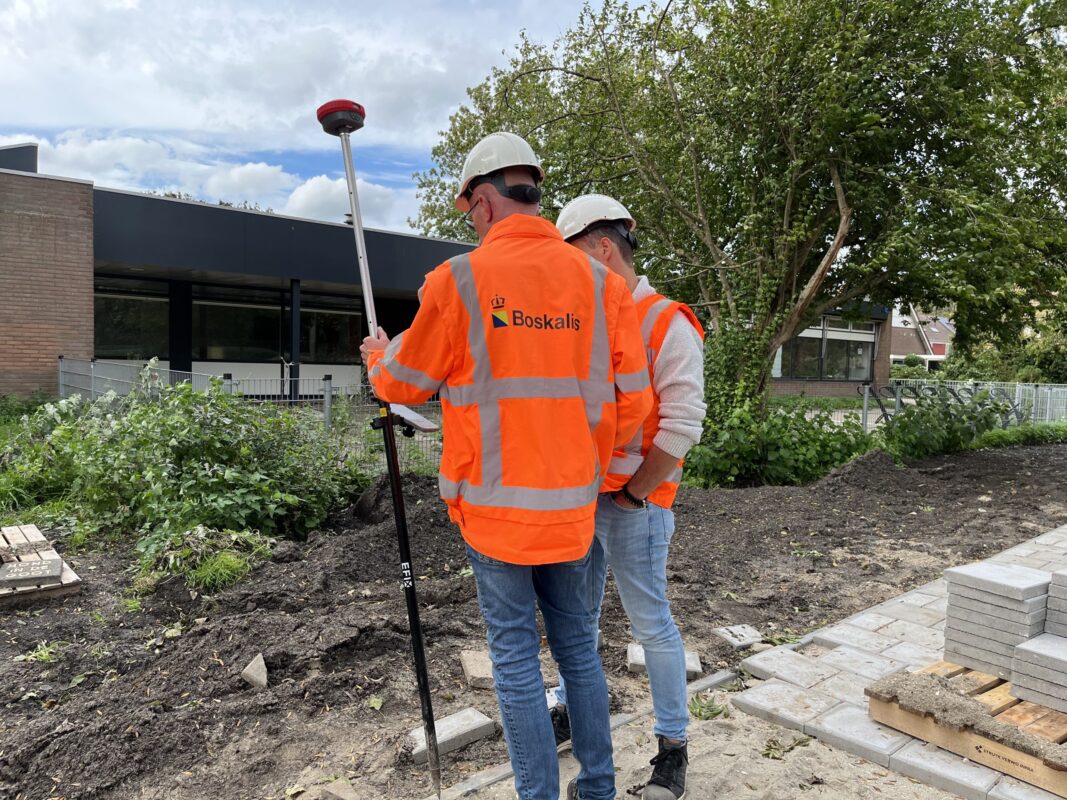
 Lidar scanning
 Total Station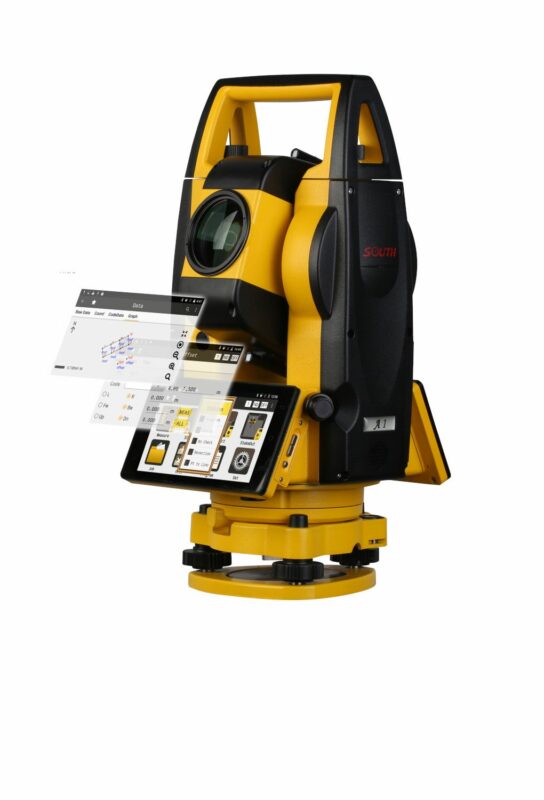
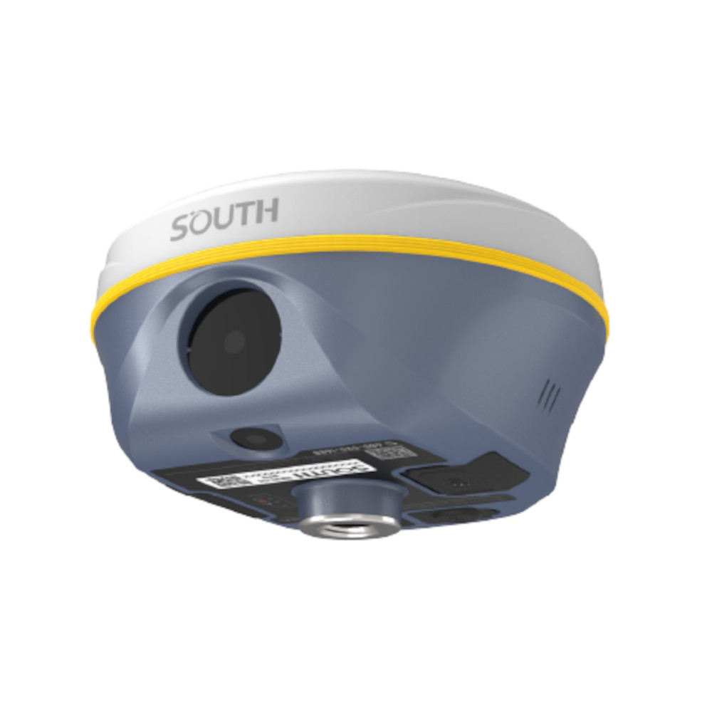
SOUTH Insight V3 Visual Positioning IMU RTK GNSS Receiver
Get the best price for your setup
Contact our experts for the best possible price and configuration.
- Fast response
- Expert configuration advice
- No overpaying for features you do not need
The SOUTH Insight V3 is a professional visual RTK GNSS receiver combining centimetre-level positioning, dual-camera surveying and calibration-free IMU tilt compensation. Its 1698-channel S805 GNSS engine tracks multiple constellations and frequencies, while the front and downward-facing cameras support visual positioning, AR-guided stakeout and image-based data collection.
During stakeout, live camera guidance helps the operator navigate towards points, lines and curves without relying only on conventional arrows and distance values. The fifth-generation IMU allows measurements with the pole tilted by up to 60°, reducing the need to keep the receiver perfectly level beside walls, around obstacles or on uneven construction sites.
The Insight V3 can receive RTK corrections through a 4G NTRIP connection or its integrated 410–470 MHz Farlink 2.0 UHF radio. Visual positioning can also be used to measure inaccessible or unsafe locations from a distance, making the receiver suitable for land surveying, construction layout, GIS mapping, utility documentation, earthworks and collecting ground data to support drone models.
SOUTH Insight V3 Highlights
| GNSS channels | 1698-channel multi-constellation and multi-frequency tracking |
|---|---|
| Camera system | Dual cameras for visual positioning and AR stakeout |
| IMU tilt surveying | Fifth-generation calibration-free IMU with compensation up to 60° |
| Visual measurement | Remote point measurement beyond 10 m under ideal conditions |
| Correction links | 4G NTRIP and integrated 410–470 MHz UHF radio |
| UHF technology | Farlink 2.0 with a stated range up to 10–12 km in ideal conditions |
| Protection | IP68 dust and water protection with 2 m pole-drop resistance |
| Battery | Internal 6800 mAh battery with up to 25 hours in rover mode |


Valued customers:









Find RTK Networks
Search NTRIP providers and connect to reliable RTK correction services.
Description
Visual RTK GNSS Surveying for Demanding Fieldwork
The SOUTH Insight V3 is an advanced RTK GNSS receiver developed for surveyors, construction professionals, engineers and GIS teams that need accurate positioning with a more visual and flexible field workflow. It combines a 1698-channel GNSS board, dual cameras, fifth-generation IMU tilt compensation and multiple correction links in one rugged receiver.
It can be used for topographic surveying, construction stakeout, road and infrastructure work, earthworks, boundary and cadastral measurement, utility mapping, GIS asset collection and ground control for drone surveys. The camera functions also provide practical options for points that cannot be occupied safely or directly with the survey pole.
Dual-Camera AR Stakeout
The Insight V3 uses front and downward-facing cameras to support augmented-reality stakeout. In compatible SOUTH field software, navigation information is placed over the live camera view, helping the operator see which direction to walk and where the design point lies in relation to the pole.
This is useful when setting out foundations, building grids, kerbs, utilities, road alignments, boundaries and other design features. Points, lines and curves can be approached using visual guidance, reducing the amount of time spent interpreting conventional compass arrows and distance values.
The downward-facing camera provides close-range guidance as the operator reaches the target. This gives the user a clearer view during the final part of the stakeout process and can make repetitive site layout easier to follow.
Visual Positioning for Inaccessible Points
Visual positioning allows the operator to calculate coordinates from photographs or video instead of physically placing the pole tip on every point. In suitable conditions, objects more than 10 metres away can be measured remotely. Actual working distance and accuracy depend on image quality, geometry, lighting, movement and the surrounding environment.
This function is valuable when measuring building façades, roof edges, trench features, points behind barriers, busy road areas, water edges or other locations that are difficult or unsafe to access. A group of images or a video can also be used to collect multiple points more efficiently than measuring each feature individually.
The recorded image information remains useful after leaving the site. Surveyors can return to the visual data when additional points or context are required, reducing the likelihood of a second visit for an overlooked feature.
Fifth-Generation IMU Tilt Compensation
The integrated IMU compensates for a pole tilt of up to 60°. The operator can place the pole tip on the required point and record the position without carefully centring the bubble for every measurement.
This speeds up routine point collection and helps around building corners, beneath vegetation, beside walls, near machinery and on sloping or uneven ground. The IMU does not rely on a magnetic compass, so nearby metal structures and other sources of magnetic interference have less effect on the tilt workflow.
Fast IMU availability also supports a smoother transition between conventional measurement, visual positioning and AR stakeout. As with every tilt-compensated system, good pole-height settings and correct field procedures remain important for dependable results.
1698-Channel Multi-Constellation GNSS Engine
The SOUTH S805 GNSS platform provides 1698 channels for tracking signals from GPS, GLONASS, Galileo, BeiDou, QZSS, SBAS and other supported services. Multi-frequency tracking gives the receiver access to a broad selection of satellite observations and helps it maintain positioning availability across varied working environments.
More available signals can support faster fixed solutions and more stable field performance near trees, buildings and other partial obstructions. Dense overhead cover and reflective surfaces can still affect every satellite receiver, so actual results depend on satellite geometry, correction quality, atmospheric conditions and the local surroundings.
Dual Positioning Algorithms
The Insight V3 includes two GNSS positioning algorithms. During unusual ionospheric conditions, network RTK users may experience a solution that appears fixed but contains an increased position error. The receiver’s enhanced positioning mode provides an alternative processing engine designed to help recognise and address this type of problem.
This feature gives survey crews an additional option when normal VRS or CORS performance becomes less predictable. It does not replace normal quality checks, control-point verification or good surveying practice, but it can improve confidence when working during difficult ionospheric periods.
4G NTRIP and Farlink 2.0 UHF
The built-in mobile modem allows the receiver to obtain RTK corrections from compatible NTRIP, CORS and VRS services. This makes it suitable for use as a network rover without setting up a local base station, provided that mobile coverage and a suitable correction subscription are available.
An integrated 410–470 MHz radio supports work with a compatible GNSS base. The Farlink 2.0 protocol is designed to carry a larger correction data stream with stable transmission over long distances. SOUTH states an operating range of up to 10–12 km in ideal conditions, although actual radio range depends on terrain, antennas, output power, interference, regulations and physical obstructions.
A lock-base function allows the rover to remain connected to the selected base when several transmitters are operating on the same frequency. The radio also supports several commonly used communication protocols for greater compatibility with existing field equipment.
Ground Data for 3D Modelling and Drone Surveys
The camera system can collect image data for supported 3D modelling workflows. Ground photographs captured with the Insight V3 can supplement aerial data where a drone cannot clearly see vertical surfaces, covered areas or features beneath overhangs.
This can help drone pilots, surveyors and engineering teams fill gaps in photogrammetric models and document excavation areas, infrastructure or urban sites from ground level. Coordinates, areas and volumes can then be handled in compatible SOUTH or third-party processing workflows, depending on the chosen software configuration.
Rugged Receiver for Everyday Site Conditions
The Insight V3 has an IP68-rated housing designed to protect the electronics against dust and temporary water immersion. It is also specified to withstand a natural 2 metre pole drop onto concrete, making it suitable for regular construction and surveying environments.
An internal 6800 mAh rechargeable battery provides up to 25 hours of operation in rover mode under stated test conditions. Battery duration in real fieldwork varies with radio use, mobile communication, camera operation, temperature and receiver settings.
The integrated colour display provides access to status information and basic configuration options. A browser-based Web UI can be opened through Wi-Fi or USB for receiver monitoring, satellite selection, base and rover setup, radio configuration, data recording, file transfer and firmware management.
Flexible Data and Integration Options
The receiver supports commonly used survey and GNSS data formats, including RTCM corrections, NMEA navigation output and RINEX static observation files. Internal storage and USB connectivity simplify the transfer of recorded field data to an office computer.
Open data interfaces and development options also allow the Insight V3 to be integrated into specialised surveying, GIS, machine or monitoring workflows where compatible software and technical resources are available.
Who Uses the SOUTH Insight V3?
Land surveyors can use the receiver for control, detail measurement, boundaries and setting out. Construction teams can position foundations, grids, utilities, kerbs and other site elements. Civil engineers can document roads, structures, earthworks and public infrastructure, while GIS teams can collect accurate coordinates and visual context for assets in the field.
Drone and photogrammetry operators can use it to establish ground control points, measure independent checkpoints and collect ground-level images that complement aerial mapping. The visual workflow is also helpful for less specialised construction personnel because it makes navigation to a stakeout point easier to understand.
Receiver Configuration and Support
This product page covers the SOUTH Insight V3 receiver rather than a complete rover set. A compatible data collector, field software, survey pole, controller bracket and RTK correction source may be required to create a complete working system.
Global GPS Systems can help select a suitable controller, software package, correction service, radio configuration and accessories for the intended country and application. This is especially important because mobile networks, UHF frequencies, coordinate systems and local surveying workflows differ between regions.
Specifications
SOUTH Insight V3 Specifications
Product Overview
| Product name | SOUTH Insight V3 |
|---|---|
| Product type | Visual-positioning multi-constellation RTK GNSS receiver |
| GNSS engine | SOUTH S805 |
| Receiver channels | 1698 |
| Operating modes | RTK rover, RTK base, network RTK, static, rapid static, PPK and standalone positioning |
| Primary applications | Land surveying, construction layout, cadastral surveying, topographic mapping, road surveying, utility surveying, control surveys, stakeout, visual measurement, photogrammetry and 3D modelling |
| Key technologies | Dual-engine positioning algorithm, dual-camera AR stakeout, visual positioning, Farlink 2.0 UHF radio, calibration-free IMU tilt compensation and video-based 3D modelling |
Satellite Tracking
| Satellite System | Supported Signals |
|---|---|
| GPS | L1, L1C, L2C, L2P and L5 |
| GLONASS | G1, G2 and G3 |
| BeiDou BDS-2 | B1I, B2I and B3I |
| BeiDou BDS-3 | B1I, B3I, B1C, B2a and B2b* |
| Galileo | E1, E5a, E5b, E6C and AltBOC* |
| QZSS | L1, L2C and L5* |
| NavIC/IRNSS | L5* |
| SBAS | L1* |
| MSS | L-Band reserved* |
| PPP services | BeiDou B2b PPP and Galileo High Accuracy Service support, subject to service availability and receiver configuration |
Positioning Accuracy
| Positioning Mode | Horizontal Accuracy | Vertical Accuracy |
|---|---|---|
| Code differential GNSS | 0.25 m + 1 ppm RMS | 0.50 m + 1 ppm RMS |
| Static GNSS | 2.5 mm + 0.5 ppm RMS | 5 mm + 0.5 ppm RMS |
| Long-observation static | 2.5 mm + 0.1 ppm RMS | 3 mm + 0.4 ppm RMS |
| Rapid static | 2.5 mm + 0.5 ppm RMS | 5 mm + 0.5 ppm RMS |
| PPK | 3 mm + 1 ppm RMS | 5 mm + 1 ppm RMS |
| UHF RTK | 8 mm + 1 ppm RMS | 15 mm + 1 ppm RMS |
| Network RTK / NTRIP | 8 mm + 0.5 ppm RMS | 15 mm + 0.5 ppm RMS |
| SBAS | Typically less than 5 m 3DRMS | |
| PPP / HAS | Approximately 10–20 cm after convergence in open conditions | Approximately 20–40 cm after convergence in open conditions |
Positioning Performance
| Position output rate | 1 Hz to 20 Hz |
|---|---|
| RTK initialization time | Typically 2–6 seconds |
| General initialization time | Less than 10 seconds under suitable conditions |
| Initialization reliability | Greater than 99.99% under suitable operating conditions |
| Dual-engine algorithm | Uses two positioning engines to improve fixed-solution reliability and performance in weak-signal, ionospheric and VRS environments |
| Weak-signal performance | High-channel-count tracking designed to improve satellite acquisition and fixed-solution performance near buildings, foliage and other obstructions |
IMU Tilt Compensation
| IMU type | Built-in fifth-generation calibration-free inertial measurement unit |
|---|---|
| Maximum tilt angle | 60° |
| IMU initialization time | Approximately 2–5 seconds of movement or walking |
| Magnetic interference resistance | Does not rely on a magnetic compass and is designed to operate in magnetically disturbed environments |
| Stationary tilt retention | Maintains the tilt solution for approximately 40 seconds while the receiver remains stationary, subject to operating conditions |
| Pole levelling | Electronic bubble display available in compatible field-controller software |
| Calibration requirement | No routine field calibration required |
Cameras and Visual Positioning
| Camera configuration | Dual-camera system |
|---|---|
| Front visual-positioning camera | 8 megapixels |
| Downward AR stakeout camera | 2 megapixels |
| AR stakeout | Camera-guided stakeout for points, lines and curves using visual directional guidance in compatible field software |
| Visual positioning | Calculates coordinates for remotely observed points from captured images or video |
| Typical remote measurement range | Up to approximately 10 m or more under ideal conditions |
| Non-contact measurement | Supports measurement of inaccessible, obstructed or hazardous points without placing the survey pole directly on the target |
| Reusable image data | Captured image data can be retained and processed again for additional point measurements |
| Visual survey applications | Suitable for measurements near roads, water, excavations, rooftops, walls, building corners, overhead obstructions and other difficult-to-reach locations |
3D Modelling and Image Processing
| 3D data capture | Supports image- and video-based data collection for three-dimensional modelling |
|---|---|
| Model outputs | Coordinates, areas, volumes and three-dimensional model data |
| UAV integration | Ground imagery can supplement UAV photogrammetry data and fill gaps in aerial survey models |
| UAV compatibility | Designed for integration with imagery from DJI and other supported UAV platforms |
| Processing workflows | Cloud-server processing, compatible desktop processing software and supported field-software workflows |
| Third-party software | Model data can be exported for use in compatible third-party modelling and mapping software |
| Coordinate configuration | Supports coordinate-parameter configuration for different project and application requirements |
Internal UHF Radio
| Radio type | Integrated UHF transmitter and receiver |
|---|---|
| Radio technology | Farlink 2.0 |
| Frequency range | 410–470 MHz |
| Supported protocols | Farlink, TrimTalk, SOUTH, HUACE, Hi-Target and Satel |
| Typical operating range | Approximately 8 km using Farlink under suitable conditions |
| Maximum stated range | Approximately 10–12 km under ideal line-of-sight conditions |
| External antenna interface | Dedicated UHF antenna connection |
| Base-lock function | Allows a rover to remain connected to a selected base when multiple transmitters operate on the same frequency |
Cellular and Wireless Connectivity
| Cellular modem | Integrated 4G modem |
|---|---|
| SIM card type | Micro-SIM |
| Wi-Fi | IEEE 802.11 b/g/n |
| Wi-Fi functions | Internet datalink, receiver hotspot and wireless Web UI access |
| Bluetooth | Bluetooth 3.0/4.1 and Bluetooth 2.1 + EDR |
| NFC | Supported for simplified pairing with compatible field controllers |
| Network RTK protocol | NTRIP |
| Network correction models | VRS, FKP and MAC |
| Selectable datalinks | Internal UHF, cellular network, Wi-Fi, Bluetooth/controller internet connection, external radio or no datalink |
Ports and Interfaces
| USB port | USB Type-C |
|---|---|
| USB functions | Charging, USB OTG, static-data transfer and Ethernet/Web UI connection |
| LEMO interface | 5-pin LEMO port |
| LEMO functions | External power input and RS-232 serial communication |
| UHF antenna port | Dedicated external-radio antenna interface |
| SIM interface | Micro-SIM card slot |
| USB Ethernet | Supported for receiver management through the internal Web UI |
Data Storage
| Internal storage | 16 GB SSD |
|---|---|
| Storage management | Automatic cyclic storage |
| External storage | External USB storage supported through USB OTG |
| Maximum recording interval | Configurable up to 20 Hz |
| USB data transfer | Plug-and-play data transmission |
| Network data download | FTP and HTTP |
| Raw-data recording | Configurable through the receiver display or internal Web UI |
Supported Data Formats
| Static observation formats | STH, RINEX 2.01, RINEX 3.02 and other supported observation formats |
|---|---|
| Differential correction formats | RTCM 2.1, RTCM 2.3, RTCM 3.0, RTCM 3.1, RTCM 3.2 and CMR |
| Position output formats | NMEA 0183, PJK plane coordinates and binary output |
| Navigation messages | Supports configurable navigation output including compatible NMEA messages |
| SOUTH observation formats | SIC Observation Data and OpenSIC Observation Data |
| External sensor input | Supported through configurable data streams |
| UAV data stream | UAVGCS data format supported |
| Network protocol | Full NTRIP support |
Receiver Software and Web UI
| Operating system | Embedded Linux |
|---|---|
| Web UI access | Available through Wi-Fi or USB connection |
| Receiver monitoring | Displays positioning status, coordinates, satellite tracking and receiver information |
| Receiver configuration | Registration, base setup, antenna setup, satellite configuration, receiver settings and system settings |
| Data-record controls | Static-data recording parameters and raw-data download |
| Data-transfer controls | NTRIP, TCP/IP and computer data-transfer configuration |
| Network controls | Cellular, Wi-Fi and related network configuration |
| Radio controls | UHF frequency, protocol and radio-modem configuration |
| Firmware updates | Receiver and modem firmware upgrade support |
| Track management | Supports recording and managing survey-track files |
| Coordinate-system setup | Supports local coordinate-system configuration |
| Online services | Real-time data upload, remote management, firmware updates and online registration through supported cloud services |
| Secondary development | Development package with OpenSIC observation-data format and interface definitions |
User Interface
| Display | 1.14-inch colour screen |
|---|---|
| Display resolution | 135 × 240 pixels |
| Physical controls | Dual-button operation |
| Status indicators | Satellite, data and power indicators |
| Battery indication | Four-stage battery indication, with each illuminated segment representing approximately 25% charge |
| Voice guidance | Supported |
| Voice languages | Chinese, English, Korean, Spanish, Portuguese, Russian, Turkish, French and Italian |
| Receiver menu functions | Work-mode selection, datalink selection, system setup and receiver-status viewing |
Sensors
| IMU | Built-in calibration-free tilt-compensation module |
|---|---|
| Visual-positioning camera | 8 MP front camera |
| AR stakeout camera | 2 MP downward-facing camera |
| Electronic bubble | Real-time pole-levelling display through compatible controller software |
| Temperature sensor | Built-in thermometer with intelligent temperature monitoring and control |
Power
| Internal battery | Built-in 6800 mAh rechargeable lithium-ion battery |
|---|---|
| Typical battery life | Up to approximately 25 hours in rover mode |
| External power input | 6–28 V DC |
| Power protection | Overvoltage protection |
| Charging interface | USB Type-C |
| Charging indicator | Status light changes from red during charging to green when fully charged |
Physical Specifications
| Dimensions | 134 mm diameter × 79.1 mm height |
|---|---|
| Weight | Approximately 800 g |
| Housing material | Magnesium-aluminium alloy |
| Form factor | Compact survey-pole-mounted GNSS receiver |
| Receiver mounting | Standard survey-pole mounting interface |
Environmental Specifications
| Ingress protection | IP68 |
|---|---|
| Water resistance | Protected against prolonged immersion at a depth of up to 1 m under specified test conditions |
| Dust resistance | Fully protected against blowing dust |
| Operating temperature | -45°C to +75°C |
| Storage temperature | -55°C to +85°C |
| Humidity | 100% non-condensing |
| Drop resistance | Designed to withstand a natural 2 m pole drop onto concrete |
| Environmental test reference | MIL-STD-810G |
Survey Functions
| Point measurement | GNSS point collection with conventional pole, tilted-pole or visual-positioning workflows |
|---|---|
| Point stakeout | Supported through compatible field software and camera-based AR guidance |
| Line stakeout | Supported |
| Curve stakeout | Supported |
| CAD stakeout | Supported through compatible survey software |
| Static surveying | Supports control surveys, densification, deformation monitoring and long-duration observation |
| Road surveying | Supports topographic measurements, profiles, cross-sections and construction layout |
| CORS operation | Compatible with supported NTRIP-based continuously operating reference-station networks |
| Visual mapping | Supports simultaneous point measurement and map-feature drawing in compatible field software |
| Preset drawing figures | Compatible software can guide measurements and automatically connect points using predefined feature shapes |
Compatible Software
| Field software | SOUTH SurvStar for Android |
|---|---|
| Desktop processing | Compatible SOUTH office and GNSS-processing software |
| 3D modelling software | Compatible SOUTH and supported third-party modelling applications |
| Controller compatibility | Compatible Android field controllers supporting the required SOUTH software and communications interfaces |
| Web-browser management | Receiver configuration through a compatible browser over Wi-Fi or USB Ethernet |
Configuration Notes
| Optional signal support | Signals marked with an asterisk may depend on firmware, licensing, satellite-service status or regional availability |
|---|---|
| Accuracy conditions | Published accuracy values assume suitable satellite geometry, correction quality, baseline length, atmospheric conditions and low multipath |
| Radio range conditions | Actual UHF range depends on antenna height, terrain, interference, radio settings, environmental conditions and line of sight |
| Battery-life conditions | Operating time varies with UHF transmission, cellular and Wi-Fi use, temperature, battery age, display use and receiver configuration |
| Visual-positioning conditions | Visual measurement range and accuracy depend on lighting, image quality, target visibility, camera geometry, GNSS status and processing workflow |
| PPP availability | PPP and high-accuracy satellite services depend on regional coverage, active satellite services and compatible receiver firmware |
Specifications and package contents may vary by configuration, region or manufacturer update. Always check the current configuration before ordering.
Reviews (0)
Only logged in customers who have purchased this product may leave a review.
FAQ
South Insight V3 FAQ
Product Overview and Applications
What is the South Insight V3?
The South Insight V3 is a professional multi-frequency RTK GNSS receiver for centimetre-level surveying, mapping and construction work. It combines multi-constellation satellite tracking, a calibration-free IMU, dual cameras, an internal UHF radio, 4G connectivity and visual positioning functions in one field-ready receiver.
Who is the South Insight V3 designed for?
The receiver is designed for land surveyors, civil engineers, construction contractors, utility companies, GIS professionals, mapping teams and infrastructure specialists who need accurate coordinates for measurement, documentation or stakeout work.
Which applications is the Insight V3 suitable for?
The Insight V3 can be used for cadastral surveys, topographic mapping, construction stakeout, road and railway projects, utility surveys, control-point measurement, earthworks, volume calculations, profiles, cross-sections, static observations, RTK surveys, PPK data collection and photogrammetric workflows.
Can the Insight V3 be used as both a base and a rover?
Yes. The Insight V3 includes an internal UHF transceiver and can be configured for base or rover operation. It can transmit corrections from a local base, receive radio corrections as a rover or connect to an NTRIP correction network using its mobile-data connection.
Can one person operate the South Insight V3?
Yes. The receiver is suitable for one-person surveying when used with a compatible data controller and field software. IMU tilt compensation, visual stakeout guidance and integrated communications help the operator collect and set out points efficiently without a second crew member.
Does the Insight V3 include a data controller and survey pole?
This product is the South Insight V3 GNSS receiver. A data controller, field software, survey pole, bracket, base accessories and other equipment may need to be selected separately unless they are specifically listed as part of the chosen package.
Accuracy, Satellites and RTK Corrections
What RTK accuracy can the South Insight V3 achieve?
The specified RTK accuracy is 8 mm plus 1 ppm horizontally and 15 mm plus 1 ppm vertically when using UHF corrections. With NTRIP corrections, the specified accuracy is 8 mm plus 0.5 ppm horizontally and 15 mm plus 0.5 ppm vertically. Actual accuracy depends on satellite visibility, correction quality, baseline length, multipath and field procedures.
How quickly can the Insight V3 obtain an RTK fixed solution?
The specified RTK initialization time is approximately 2 to 8 seconds under suitable conditions, with general initialization stated as under 10 seconds. Trees, buildings, interference, poor satellite geometry and correction interruptions can increase initialization time.
Which satellite constellations does the Insight V3 track?
The 1,698-channel receiver tracks multiple frequencies from GPS, GLONASS, Galileo and BeiDou. It also supports selected QZSS, SBAS, IRNSS or NavIC and other signals where available, helping provide strong satellite availability in challenging environments.
Can the Insight V3 work near buildings or beneath trees?
Yes. Its 1,698-channel GNSS board is designed to track a large number of satellite signals, including weaker signals. This can improve fixed-solution availability near buildings and vegetation, although dense obstructions and reflective surfaces may still reduce accuracy or prevent reliable positioning.
Does the Insight V3 support NTRIP and CORS networks?
Yes. The receiver supports the NTRIP protocol and network correction models including VRS, FKP and MAC. A compatible correction-service subscription, SIM card or controller internet connection, mountpoint and correct coordinate-system configuration are required.
What is the UHF radio range of the South Insight V3?
The internal 410–470 MHz UHF radio typically supports a range of around 8 km. Farlink 2.0 can reach approximately 10–12 km under ideal conditions. Practical range depends on terrain, vegetation, buildings, antenna height, radio power, interference and local radio regulations.
IMU, Cameras and Smart Surveying Functions
What does the 60-degree IMU tilt compensation do?
The integrated IMU compensates for a survey pole tilted by up to 60 degrees. This allows the operator to measure points without keeping the pole perfectly vertical, making it easier to work beside walls, beneath obstacles, on slopes and in other difficult locations.
Does the Insight V3 IMU require manual calibration?
The built-in IMU is designed to be calibration-free during normal use. It initializes through natural movement in the field, reducing setup time. Reliable tilt measurements still require suitable GNSS tracking, correct pole-height settings and a stable RTK solution.
What is dual-camera AR stakeout?
Dual-camera AR stakeout uses the receiver’s front and downward-facing cameras to display directional guidance over a live image in compatible field software. The guidance helps the operator navigate toward points, lines and curves before accurately positioning the pole at the target.
What is visual positioning on the Insight V3?
Visual positioning combines GNSS coordinates, camera imagery, IMU information and photogrammetric processing to calculate coordinates for features visible in photographs or video. It can be useful when a point is difficult, unsafe or impossible to reach directly with the survey pole.
Which points can be measured using visual positioning?
Visual positioning can help measure building corners, façades, roof edges, points behind fences, trenches, busy-road features and other inaccessible targets. Results depend on the distance, lighting, image quality, target visibility, camera geometry and GNSS solution quality.
Can the Insight V3 collect data for 3D models?
Yes. The receiver can collect georeferenced imagery for photogrammetric and 3D-modelling workflows when used with compatible software. These functions can support site documentation, excavation surveys, accident-scene recording, volume calculations and the completion of areas missing from UAV datasets.
Hardware, Connectivity and Data Management
How long does the South Insight V3 battery last?
The built-in 6,800 mAh rechargeable lithium-ion battery is specified for up to approximately 18 hours in rover mode. Actual operating time varies with UHF use, mobile-data activity, camera functions, temperature, Bluetooth connections and battery condition.
Is the Insight V3 waterproof and dustproof?
Yes. The receiver has an IP68 rating, providing protection against dust and water immersion under the manufacturer’s specified test conditions. It is built for demanding outdoor surveying environments, but ports and covers must be correctly closed to maintain protection.
Can the Insight V3 withstand accidental drops?
The magnesium-aluminium alloy housing is designed to withstand a natural two-metre pole drop onto concrete. This improves field durability, although using proper transport protection and avoiding impacts remains important for accuracy and equipment life.
Which communication options are available?
The Insight V3 supports internal UHF radio, 4G mobile data, Bluetooth, Wi-Fi, NFC, USB Type-C, Ethernet through a compatible adapter and serial communication through its LEMO interface. Available connections support controller communication, NTRIP corrections, receiver configuration and data transfer.
How much internal storage does the Insight V3 have?
The receiver has 16 GB of internal storage with automatic cycling. It also supports external USB storage through OTG, configurable recording rates up to 20 Hz and data transfer through USB, FTP or HTTP-based functions.
Which survey data formats does the Insight V3 support?
Supported formats include STH and RINEX 2.01 or 3.02 for static data, RTCM 2.1 through RTCM 3.2 for differential corrections and NMEA 0183, plane-coordinate, binary and Trimble GSOF output formats. Import and export options also depend on the field software being used.

 GPS & GNSS
 Total Stations
 Data collectors
 Software
 Correction services
 Machine control
 External radio
 Marine
 Accessories
Reviews
There are no reviews yet