
 GPS & GNSS
 Lidar scanning
 Total Station
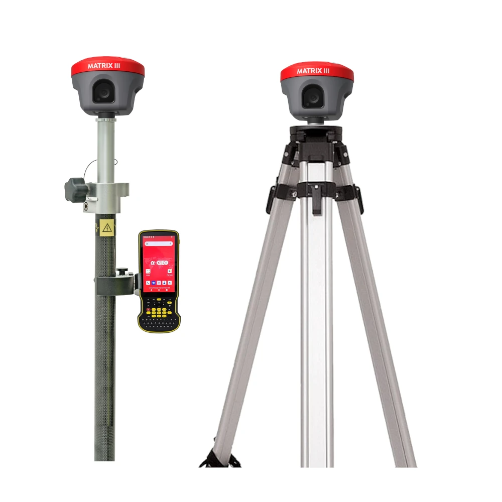
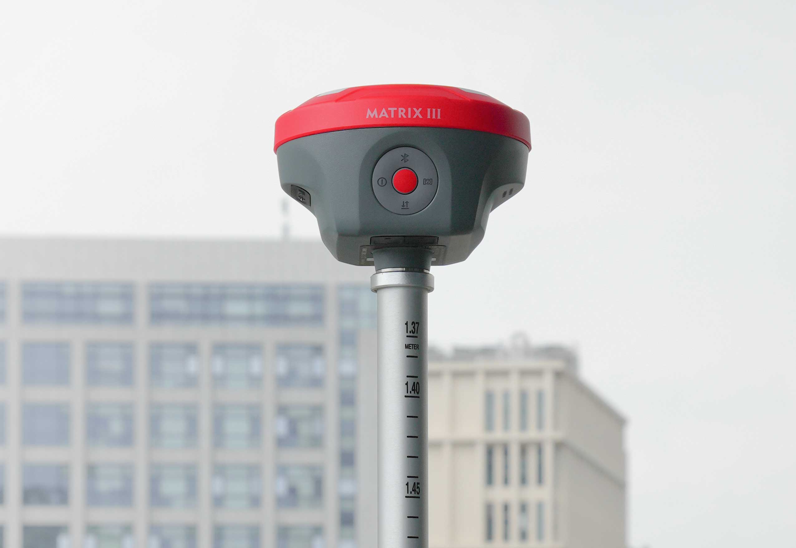
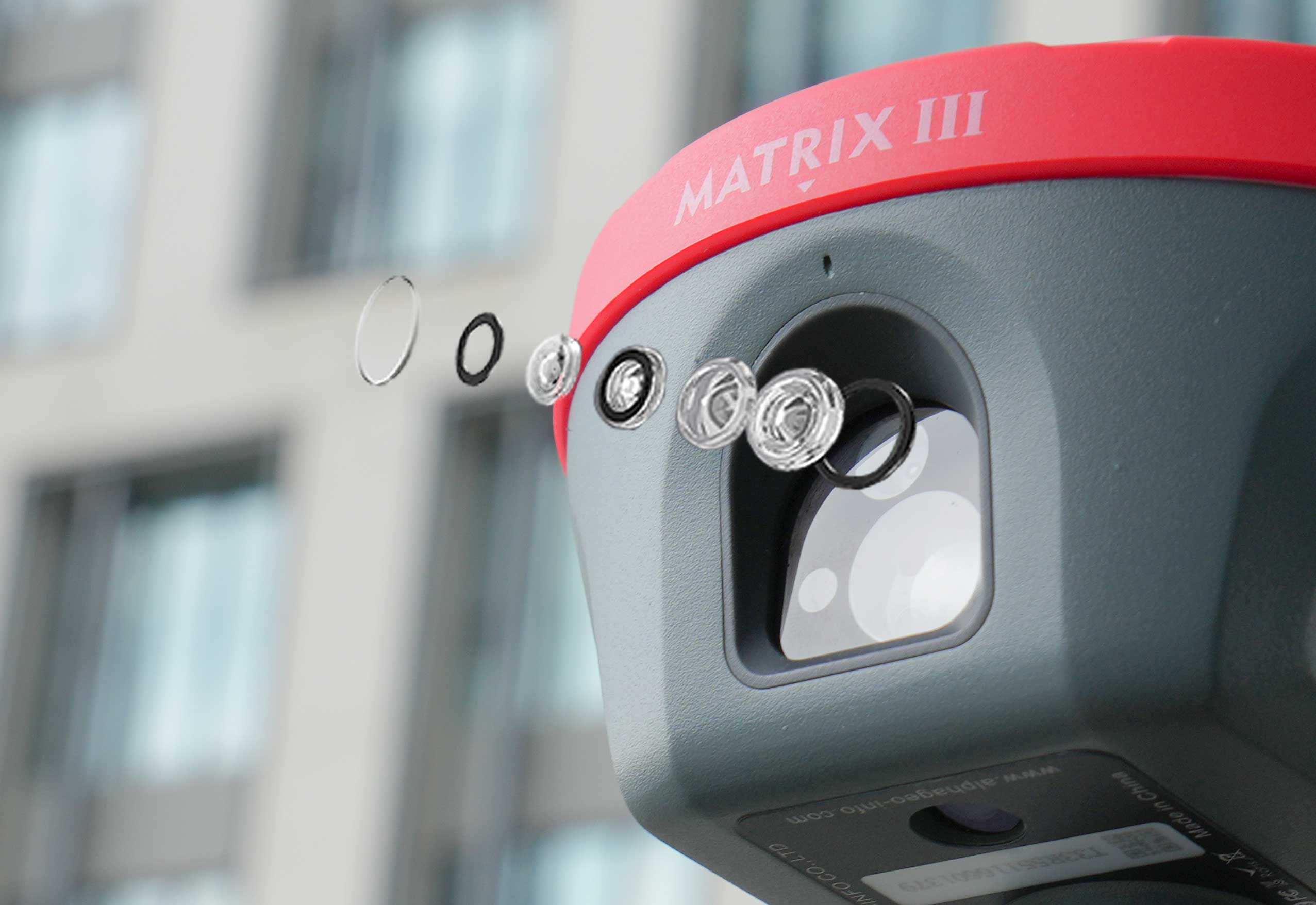



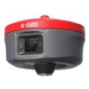
a GEO Matrix III Laser AR IMU Rover Base Set
This product is available
Get the best price for your setup
Contact our experts for the best possible price and configuration.
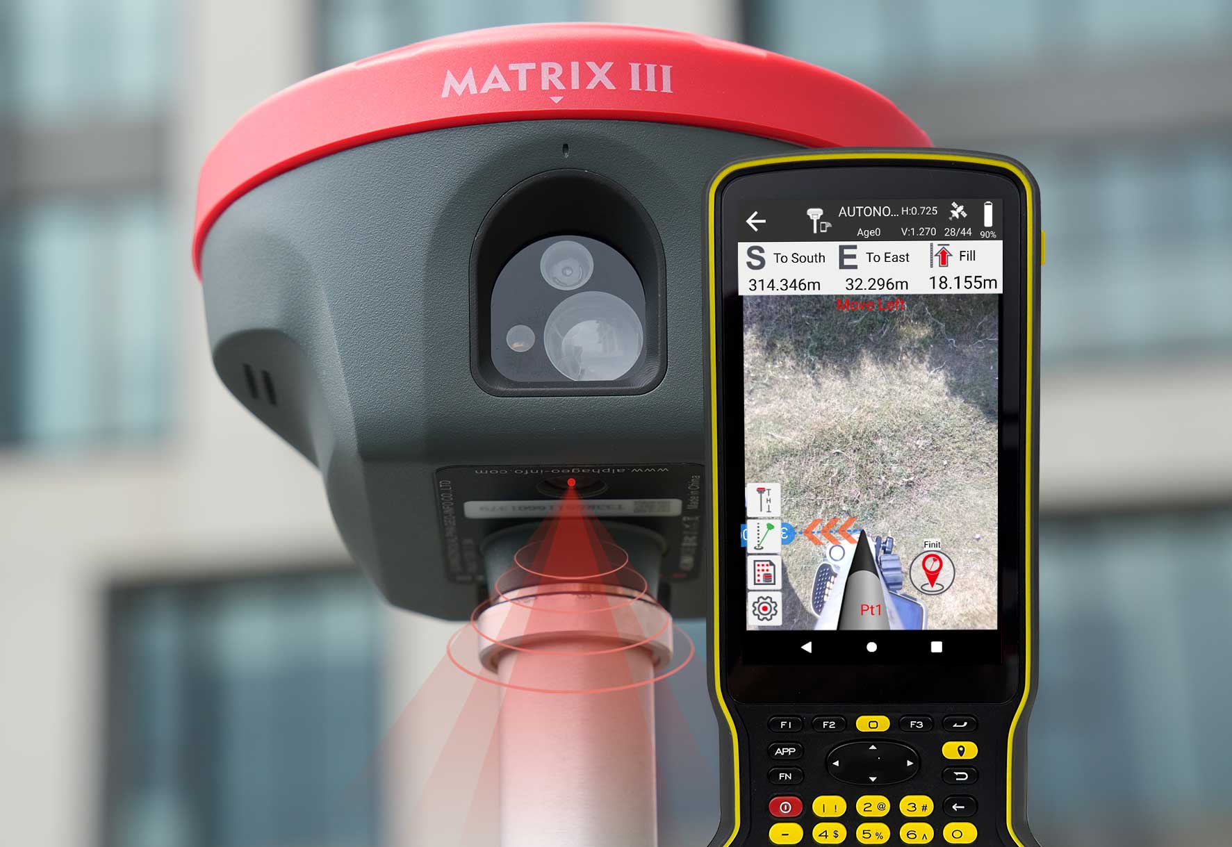
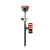
The a-GEO Matrix III Rover & Base Set is a complete RTK GNSS solution for surveyors, construction teams, GIS users, drone pilots and engineering crews who want to work independently without always relying on an RTK network. The set combines advanced Matrix III GNSS receivers with laser surveying, AR real-scene stakeout, 120° IMU tilt compensation, 1408-channel multi-constellation tracking and integrated UHF communication.
With one receiver used as the base and the other as the rover, field teams can create their own local correction setup for accurate topographic surveys, construction layout, control work, earthworks, drone ground control points and general site measurement. The included S60III rugged data collector gives operators a practical Android field controller with a physical keyboard, bright display, 4G, WiFi and long battery life.
a-GEO Matrix III Rover & Base Set Highlights
| Set Type | Complete RTK rover and base GNSS set |
|---|---|
| Laser Surveying | 0.05 m to 100 m laser measurement range |
| IMU Tilt | 0° to 120° tilt compensation |
| AR Stakeout | Real-scene AR stakeout for faster point location |
| GNSS Channels | 1408 channels with GPS, GLONASS, Galileo, BeiDou, QZSS, IRNSS and SBAS |
| Base Rover Communication | Integrated 410 to 470 MHz UHF radio |


Valued customers:









Find RTK Networks
Search NTRIP providers and connect to reliable RTK correction services.
Description
a-GEO Matrix III Rover & Base Set for Independent RTK Surveying
The a-GEO Matrix III Rover & Base Set is a complete GNSS surveying package for professionals who need accurate RTK positioning without depending only on a correction network. By using one Matrix III receiver as a base and the second as a rover, surveyors and construction crews can set up their own local RTK correction system on site.
This makes the set a practical choice for land surveying, construction layout, civil engineering, road projects, earthworks, GIS mapping, drone ground control and site measurement in areas where mobile RTK coverage may be limited or where a project-specific base station is preferred.
Complete Rover and Base Workflow
A rover and base set gives field teams more control over their RTK setup. The base receiver is placed over a known or temporary control point and sends corrections to the rover, allowing the operator to measure and stake out with centimetre-level RTK positioning in the field.
For contractors and survey teams working on larger sites, rural projects, infrastructure corridors or locations with unreliable network corrections, this setup can be more dependable than using a rover alone. It is also useful when a project requires repeatable local coordinates or when multiple crews need to work from the same site control.
100 m Laser Measurement for Hard-to-Reach Points
The Matrix III receiver includes a laser measurement module with a range from 0.05 m to 100 m. In real fieldwork, this helps when a point cannot be occupied directly with the survey pole. Building corners, road edges, walls, fences, trenches, slopes, stockpile boundaries and unsafe areas can often be measured from a more convenient position.
For construction workers, surveyors and GIS crews, laser-assisted measurement reduces the need for awkward pole placement and extra setups. It is especially useful on busy job sites, near traffic, around machinery or in locations where access is restricted.
AR Real-Scene Stakeout
AR real-scene stakeout helps users find points faster by showing guidance over the live field view. Instead of only following distance values and direction arrows, the operator can see the stakeout direction in relation to the real environment.
This is useful for construction layout, road marking, utility work, boundary points and site preparation. It can make stakeout easier for less experienced users while still helping professional surveyors complete repetitive layout work more efficiently.
120° IMU Tilt Compensation
The Matrix III supports IMU tilt compensation up to 120°. This allows the rover pole to be tilted while measuring or staking out, which is helpful near walls, under obstacles, next to fences, beside machines or in other places where holding the pole perfectly vertical is difficult.
The IMU is designed for fast initialization and calibration-free use, helping crews keep moving instead of stopping repeatedly to re-level the pole. For daily topographic work, as-built checks and construction layout, this can save time and make awkward points easier to capture.
Multi-Constellation GNSS Performance
The a-GEO Matrix III uses a 1408-channel GNSS board and tracks GPS, GLONASS, Galileo, BeiDou, QZSS, IRNSS and SBAS signals. This broad satellite support helps maintain positioning performance in open areas and improves availability when working near buildings, trees or other partial obstructions.
The receiver supports RTK surveying, network RTK, static GNSS work and PPP technology. In a rover and base setup, the integrated UHF radio allows the base receiver to send corrections directly to the rover over the field radio link.
Integrated UHF, 4G, WiFi and Bluetooth
The Matrix III is built with flexible communication options for different field setups. The integrated UHF radio supports 410 to 470 MHz base-rover communication, while the 4G modem can be used for mobile correction services where available. WiFi, Bluetooth, USB Type-C, SIM support and web UI configuration give users practical ways to connect, configure and manage the equipment.
This flexibility is important for survey teams that move between different projects. The same set can be used as a local base-rover system, a network RTK rover setup or a static GNSS observation system depending on the job.
S60III Rugged Data Collector Included
The included a-GEO S60III rugged data collector is designed for GNSS fieldwork and mapping. It runs Android 12 with GMS support and uses a Qualcomm SDM 662 octa-core processor, 4 GB RAM and 64 GB internal storage. The 5.5-inch 1920 x 1080 display offers 500 nit brightness for outdoor readability, while the physical QWERTY keyboard makes data entry easier in wet, dusty or glove-use conditions.
The S60III includes Bluetooth 5.0, dual-band WiFi, 4G network support, USB Type-C with OTG, NFC and a 9000 mAh battery. Its IP68 rating and rugged housing make it suitable for demanding site conditions, from construction projects to long mapping days in the field.
Built for Outdoor Survey Conditions
The Matrix III receiver uses a magnesium alloy body and is rated IP67 for dust and water protection. It is designed to operate from -40°C to +75°C and withstand a 2 m pole drop onto concrete. This makes it suitable for tough environments where equipment may face rain, dust, mud, vibration and frequent transport between job sites.
The receiver includes 64 GB internal storage with cyclic storage support, which is useful for static observations and long data collection sessions. Battery life is rated up to 12 hours in rover mode, 7 hours in base mode and 15 hours in static mode, depending on the workflow and communication settings.
Who Is This Rover and Base Set For?
The a-GEO Matrix III Rover & Base Set is well suited for surveyors, civil engineering contractors, construction layout teams, GIS mapping crews, drone pilots and companies that want a complete RTK GNSS setup. It is especially useful for users who work outside reliable RTK network coverage, need their own local control, or want one package that can handle base-rover work, laser measurement, AR stakeout and tilted-pole measurement.
Surveyors can use it for topographic surveys, cadastral work, control points and as-built checks. Construction crews can use it for layout, level checks, road edges, earthworks and site verification. Drone pilots can use it to measure ground control points and checkpoints, while GIS teams can collect accurate asset locations in the field.
Buying from Global GPS Systems
Global GPS Systems supplies the a-GEO Matrix III Rover & Base Set with worldwide delivery and support from GNSS product specialists. This helps buyers choose the right configuration, accessories, controller setup and correction workflow for their projects. Whether you are upgrading an older GNSS kit or building a complete RTK setup for independent fieldwork, this rover and base set gives you a modern combination of laser surveying, AR stakeout, IMU tilt and professional GNSS performance.
Datasheets & Manuals
Datasheets and manuals
Specifications
a-GEO Matrix III Rover & Base Set Specifications
Product Overview
| Product Name | a-GEO Matrix III Rover & Base Set |
|---|---|
| Product Type | Professional RTK GNSS rover and base set with laser measurement, AR stakeout, camera support and IMU tilt compensation |
| Main Receiver | a-GEO Matrix III GNSS RTK receiver |
| Set Configuration | Rover and base RTK GNSS setup for local base correction workflows |
| Controller | S60III rugged Android data collector |
| Field Software | SurPro 6.0 Android field software |
| Primary Applications | Land surveying, topographic measurement, construction layout, engineering measurement, infrastructure work, GIS data collection, utility mapping, road stakeout, cadastral work, base-rover RTK operation and hard-to-reach point measurement |
| Key Features | 100 m laser measurement, AR real-scene stakeout, 5 MP laser-assisted camera, 5 MP AR camera, 1408-channel GNSS board, 120° IMU tilt compensation, internal UHF radio, 4G modem, WiFi, Bluetooth and 64 GB internal receiver storage |
Receiver GNSS Performance
| GNSS Channels | 1408 channels |
|---|---|
| GPS Signals | L1 C/A, L2C, L2P, L5 |
| GLONASS Signals | L1, L2 |
| BeiDou / BDS Signals | B1, B1C, B2, B2a, B2b, B3 |
| Galileo Signals | E1, E5a, E5b, E6 |
| QZSS Signals | L1, L2, L5, L6 |
| SBAS Support | WAAS, EGNOS, MSAS, GAGAN, SDCM |
| Supported Constellations | GPS, GLONASS, BDS, Galileo, QZSS, IRNSS and SBAS |
| PPP Support | Supports PPP technologies including BDS PPP and Galileo HAS |
| Cold Start | <60 s |
| Hot Start | <15 s |
| Positioning Output Rate | 1 Hz to 50 Hz |
| Signal Reacquisition | <1 s |
| RTK Initialization Time | <5 s |
| Initialization Reliability | >99.99% |
| Time Accuracy | 20 ns |
Receiver Positioning Accuracy
| Mode | Horizontal Accuracy | Vertical Accuracy |
|---|---|---|
| Code Differential GNSS Positioning | 0.25 m + 1 ppm RMS | 0.50 m + 1 ppm RMS |
| Static GNSS Surveying | 2.5 mm + 0.5 ppm RMS | 5 mm + 0.5 ppm RMS |
| RTK Surveying, Baseline <30 km | 8 mm + 1 ppm RMS | 15 mm + 1 ppm RMS |
| Network RTK | 8 mm + 0.5 ppm RMS | 15 mm + 0.5 ppm RMS |
Laser Measurement
| Laser Measurement Range | 0.05 m to 100 m |
|---|---|
| Laser Measurement Accuracy | ±2 mm + 100 × 10-6 × D, where D is the measuring distance in mm |
| Laser Survey Function | Laser-assisted coordinate measurement for difficult, unsafe or hard-to-reach points |
| Typical Laser Use Cases | Building corners, walls, fences, slopes, drainage edges, stockpiles, traffic areas, hard surfaces and areas where occupying the point with a pole is slow or impractical |
IMU and Tilt Compensation
| IMU Support | Supported |
|---|---|
| IMU Initialization | 4D IMU initialization in 3 seconds |
| IMU Update Rate | 400 Hz |
| Tilt Compensation Range | 0° to 120° |
| Tilt Accuracy | <2.5 cm within 120° |
| Calibration | Calibration-free IMU operation |
| Magnetic Interference Resistance | Designed to be immune to magnetic interference |
Camera and AR Stakeout
| Laser-Assisted Camera | 5 MP HD camera |
|---|---|
| AR Camera | 5 MP |
| Field of View | 84° |
| Lens | f/2.08 mm large-aperture lens |
| Low-Light Target Capture | Designed to capture target feature points in illumination below 500 lux |
| AR Real-Scene Stakeout | Supported, with real-world camera guidance and directional arrows for stakeout work |
| Camera-Assisted Workflow | Supports visual targeting to reduce blind aiming during laser-assisted coordinate positioning |
Receiver Communications
| Internal UHF Radio | 1.5 W receiver and transmitter |
|---|---|
| UHF Frequency Band | 410 MHz to 470 MHz, supports frequency modification |
| UHF Protocols | Trimtalk450S, Alphatalk15, South, Satel, PCC-EOT |
| Cellular Network | Full-frequency multi-band 4G modem |
| Cellular Standards | TDD-LTE, FDD-LTE, WCDMA, CDMA2000 |
| WiFi | 802.11 b/g, access point and client mode, supports hotspot access for correction transmission |
| Bluetooth | Bluetooth 5.2 classical/BLE proprietary dual-mode |
| Differential Data Formats | RTCM2x, RTCM3x, CMR, CMR+, sCMRx |
| GNSS Output Data Formats | RINEX, NMEA-0183 |
Receiver I/O Interfaces
| LEMO Port | 1 × 5-pin LEMO port for power supply, RS232 and external radio communication |
|---|---|
| USB Port | 1 × USB Type-C port for charging and data download |
| SIM Card Slot | 1 × Nano SIM card slot |
| UHF Antenna Interface | 1 × UHF antenna interface |
Receiver Data Storage
| Internal Memory | 64 GB |
|---|---|
| Cyclic Storage | Supported |
| Raw Observation Storage Capacity | Almost 4 years based on 5-second sampling interval |
| Storage Design | Embedded memory chip for observation data safety |
Receiver Electrical
| External Power Input | 9 V to 24 V DC external power input to 5-pin LEMO port |
|---|---|
| USB Charging | Supports USB Type-C fast charging |
| Battery | Built-in 7000 mAh, 7.4 V Li-ion battery |
| Battery Life – Rover Mode | 12 hours |
| Battery Life – Base Mode | 7 hours |
| Battery Life – Static Mode | 15 hours |
Receiver Physical and Environmental
| Housing Material | Magnesium alloy |
|---|---|
| Dimensions | 129 mm × 129 mm × 99 mm |
| Weight | <0.8 kg |
| Operating Temperature | -40°C to +75°C |
| Storage Temperature | -55°C to +85°C |
| Waterproof and Dustproof Rating | IP67 standard, protected from 30-minute immersion to a depth of 1 m |
| Shock Resistance | Survives a 2 m pole drop onto concrete |
| Vibration | MIL-STD-810G |
| Humidity | 100% non-condensing |
Receiver User Interaction
| Operating System | Linux OS |
|---|---|
| Buttons | Power key |
| Indicators | Power indicator, Bluetooth indicator, satellite indicator and data link indicator |
| Voice Prompts | Intelligent voice prompts |
| Web UI | Supports Web UI configuration |
Base and Rover Workflow
| RTK Rover Operation | Supported |
|---|---|
| RTK Base Operation | Supported |
| Base-to-Rover Correction Link | Supported using internal UHF radio |
| Network RTK Operation | Supported using 4G, WiFi hotspot or controller connectivity depending on workflow |
| Static GNSS Surveying | Supported |
| Laser Survey | Supported up to 100 m |
| AR Real-Scene Stakeout | Supported |
| Tilt Surveying | Supported up to 120° tilt compensation |
S60III Data Collector System
| Operating System | Android 12 with GMS support |
|---|---|
| CPU | Qualcomm SDM 662 octa-core, 2.0 GHz |
| RAM | 4 GB SDRAM |
| Internal Flash Memory | 64 GB |
| Memory Card Support | MicroSDHC up to 128 GB |
| Field Software Support | SurPro 6.0 field software |
S60III Data Collector Display and Input
| Display Size | 5.5 in |
|---|---|
| Display Type | IPS LCD capacitive multi-touch display |
| Display Resolution | 1920 × 1080 pixels, HD+, 401 ppi |
| Display Brightness | 500 nit |
| Display Protection | Gorilla Glass |
| Keypad | QWERTY key layout |
| Keyboard Design | Standard English keyboard with shortcut buttons |
S60III Data Collector Communications
| SIM Card Type | Nano SIM card |
|---|---|
| GSM Bands | 850 / 900 / 1800 / 1900 MHz |
| WCDMA Bands | B1 / B2 / B4 / B5 / B8 |
| LTE-TDD Bands | B34 / B38 / B39 / B40 / B41 |
| LTE-FDD Bands | B1 / B2 / B3 / B4 / B5 / B7 / B8 / B12 / B13 / B17 / B20 / B25 / B26 / B28 |
| WiFi | 802.11 a/b/g/n/ac, access point mode, 2.4 GHz / 5 GHz |
| Bluetooth | Bluetooth 5.0 |
| USB | USB Type-C, OTG supported |
| NFC | Supported |
| GNSS / A-GPS | GNSS support for BDS, GPS and GLONASS; A-GPS supported |
S60III Data Collector Sensors and Multimedia
| Rear Camera | 13 MP rear camera with autofocus and flash |
|---|---|
| G-Sensor | Supported |
| Gyroscope | Supported |
| E-Compass | Supported |
| Light Sensor | Supported |
| Speaker | Supported |
| Microphone | Supported |
S60III Data Collector Electrical
| Battery Type | Li-ion battery |
|---|---|
| Battery Capacity | 9000 mAh |
| Operating Time | 22 hours |
| Charging Time | 4 hours typical |
S60III Data Collector Physical and Environmental
| Dimensions | 228 mm × 96 mm × 21 mm |
|---|---|
| Weight | 420 g with battery |
| Operating Temperature | -20°C to +65°C |
| Storage Temperature | -30°C to +70°C |
| Dust and Water Protection | IP68 |
| Humidity | 5% to 95% non-condensing |
| Shock and Vibration | 1.2 m / 4 ft fall onto concrete |
S60III Data Collector Certifications and Accessories
| Certifications | CE, FCC |
|---|---|
| Standard Accessories | A/C charger, USB cable, stylus and hand strap |
Supported Field Software Functions
| Point Collection | Supported |
|---|---|
| Stakeout | Supported |
| CAD-Based Field Work | Supported |
| Engineering Measurement | Supported |
| RTK Correction Connection | Supports field connection to receiver corrections and RTK network workflows |
| Survey Result Export | Supported through field software workflow |
Package Contents
| Item | Quantity | Notes |
|---|---|---|
| a-GEO Matrix III GNSS Receiver | 2 | Configured for rover and base operation |
| S60III Rugged Data Collector | 1 | Android field controller for receiver control, data collection and stakeout workflows |
| SurPro 6.0 Field Software | 1 | Android field software for survey, stakeout and engineering workflows |
| Receiver Charger Adapter and Cable | 2 sets | For Matrix III receiver charging |
| Radio Antenna | 2 | For internal UHF radio operation |
| Receiver Carrying Case | 2 | Transport and storage case for each receiver |
| Data Collector A/C Charger | 1 | Standard S60III accessory |
| Data Collector USB Cable | 1 | Standard S60III accessory |
| Stylus | 1 | Standard S60III accessory |
| Hand Strap | 1 | Standard S60III accessory |
Accuracy and Reliability Notes
| GNSS Accuracy Conditions | Precision and reliability may be affected by multipath, obstruction, satellite geometry and atmospheric conditions. |
|---|---|
| Long Baseline Recommendation | For baselines longer than 30 km, use precise ephemeris and occupation up to 24 hours for high-precision static GNSS. |
| SBAS Accuracy Note | SBAS positioning performance depends on SBAS system performance. |
| Network RTK Note | Network RTK ppm values are referenced to the closest physical base station and depend on network performance. |
| Controller Operating Time Note | S60III operating time may vary based on temperature, connectivity, display brightness and field software usage. |
Specifications and package contents may vary by configuration, region or manufacturer update. Always check the current configuration before ordering.
FAQ
a-Geo Matrix III Rover & Base Set FAQ
Product Overview
What is the a-Geo Matrix III Rover & Base Set?
The a-Geo Matrix III Rover & Base Set is a professional RTK GNSS surveying system with a rover receiver and base station workflow. It is designed for accurate field positioning, point collection, stakeout, construction layout, mapping, infrastructure work and other geospatial measurement tasks.
Who is the Matrix III Rover & Base Set designed for?
This rover and base set is designed for land surveyors, construction layout crews, civil engineers, GIS teams, utility mapping professionals, infrastructure contractors, road and railway projects, earthworks teams and drone mapping users who need reliable RTK positioning in the field.
What is the difference between a rover set and a rover/base set?
A rover set uses one GNSS receiver as the mobile field unit and usually receives corrections from an RTK network, NTRIP service or existing base station. A rover/base set includes a rover and a base workflow, allowing the user to create a local correction source for the rover on site.
Why would I choose a rover/base set instead of a rover-only setup?
A rover/base set is useful when there is no reliable RTK network available, when mobile internet coverage is poor, or when you want to work independently from third-party correction services. It is especially practical for remote sites, private construction projects, rural surveys, quarries, agriculture, infrastructure corridors and large project areas.
What types of work can the Matrix III Rover & Base Set be used for?
The Matrix III Rover & Base Set can be used for land surveying, topographic measurement, construction stakeout, road and railway layout, utility mapping, earthworks, terrain measurement, stockpile measurement, drone ground control points, cadastral work, engineering control and GIS data collection.
RTK, GNSS and Rover/Base Workflow
How does the rover and base workflow work?
In a rover and base workflow, the base receiver is placed on a fixed point, tripod, benchmark or known control position. The base calculates correction data and sends it to the rover. The rover then uses those corrections to calculate accurate RTK positions while the operator moves around the project area.
Can the Matrix III Rover & Base Set work without an RTK network?
Yes. One of the main reasons to use a rover/base set is to work without depending on a public RTK network or NTRIP service. With your own base station, you can create a local correction source for the rover, depending on the site setup, radio range and project requirements.
Does the Matrix III support RTK surveying?
Yes. The Matrix III is an RTK GNSS receiver designed for centimetre-level positioning when used with a suitable correction source. Correction data can come from the included base workflow, a compatible base station, radio corrections or a supported RTK network.
Which satellite constellations does the Matrix III support?
The Matrix III supports multi-constellation GNSS tracking, including GPS, GLONASS, Galileo and BeiDou. Published specifications also list support for QZSS, IRNSS and SBAS, helping maintain reliable satellite availability in a wide range of field environments.
How many GNSS channels does the Matrix III have?
The Matrix III uses a 1408-channel GNSS engine. This high channel count helps the receiver track signals across multiple satellite constellations and supports stable positioning performance during professional RTK fieldwork.
Does the Matrix III Rover & Base Set have UHF radio?
Yes. The Matrix III includes UHF radio communication in the 410 to 470 MHz range. This allows correction data to be transmitted between base and rover in radio-based RTK workflows, depending on local regulations, terrain, antenna setup and site conditions.
Does the Matrix III support 4G and NTRIP corrections?
Yes. The Matrix III includes a 4G internet modem and can be used with compatible NTRIP correction services where mobile network coverage is available. This gives users flexibility to work with both local base corrections and network RTK workflows.
Laser, Camera, AR Stakeout and IMU
What is the 100 m laser measurement function used for?
The 100 m laser measurement function is used to capture points that are difficult, unsafe or inefficient to reach directly with a GNSS pole. It is useful for building corners, walls, fences, slopes, stockpiles, drainage edges, traffic areas, restricted zones and other hard-to-reach features.
How far can the Matrix III laser measure?
The Matrix III laser has a specified maximum measurement range of up to 100 meters. This allows field users to measure remote targets while staying in a safer or more practical position.
What is AR real-scene stakeout?
AR real-scene stakeout uses a live camera view with visual guidance to help the operator find and mark design points in the real field environment. This can make stakeout easier to understand than using only arrows, numbers or map offsets.
How does AR stakeout help construction and survey teams?
AR stakeout helps users move directly toward the required point and mark it more efficiently. It can reduce repeated back-and-forth adjustments during construction layout, road work, utility stakeout, earthworks and other projects with many points to mark.
What is the 5MP auxiliary camera used for?
The 5MP auxiliary camera supports laser-assisted coordinate positioning by helping the user identify and aim at target features more clearly. It improves target capture in complex environments and helps avoid blind aiming during laser measurement.
Does the Matrix III support IMU tilt compensation?
Yes. The Matrix III supports IMU tilt compensation up to 120 degrees. This allows users to collect or stake points without keeping the pole perfectly vertical for every observation, which is useful near obstacles, fences, walls, trenches, vegetation and machinery.
Does the IMU need calibration?
The Matrix III is designed with a fast-initializing, calibration-free IMU that is also described as resistant to magnetic interference. This helps reduce setup time and supports faster field measurement workflows.
Controller, Connectivity and Field Use
What data collector is used with the Matrix III Rover & Base Set?
The Matrix III Rover & Base Set is paired with the S60III RTK data collector. This rugged controller is designed for outdoor GNSS work and supports professional field measurement, mapping and stakeout workflows.
What connectivity options does the S60III controller provide?
The S60III data collector includes Bluetooth, dual-band Wi-Fi and 4G connectivity. These communication options help connect the controller with GNSS receivers, correction services, RTK networks and field data workflows.
Is the Matrix III Rover & Base Set suitable for remote locations?
Yes. The rover/base workflow is especially useful for remote projects, rural surveys, large sites and areas where RTK network coverage or mobile internet is unreliable. By using a local base station, field teams can create their own correction source on site.
Can the Matrix III be used around obstacles?
Yes. The combination of laser measurement, 120-degree IMU tilt compensation, AR stakeout and camera support makes the Matrix III useful around walls, fences, slopes, traffic zones, machinery, vegetation, trenches and other obstacles where conventional pole positioning can be slow or difficult.
Is the Matrix III Rover & Base Set built for professional field conditions?
Yes. The Matrix III is built for demanding surveying and construction environments. Its professional GNSS hardware, UHF radio, 4G connectivity, laser module, camera support and rugged field workflow make it suitable for daily use on outdoor project sites.
What accessories are normally used with a rover/base set?
Typical rover/base accessories include GNSS receivers, a data collector, field software, survey pole, tripod, tribrach or base setup accessories, brackets, antennas, chargers, cables, carrying case and other items required for rover and base field operation. Exact package contents can vary by configuration.
Reviews (0)
Only logged in customers who have purchased this product may leave a review.
 GPS & GNSS
 Total Stations
 Data collectors
 Software
 Correction services
 Machine control
 External radio
 Lasers & levellers
 Marine
 Accessories
Reviews
There are no reviews yet