

 GPS & GNSS
 Lidar scanning
 Total Station
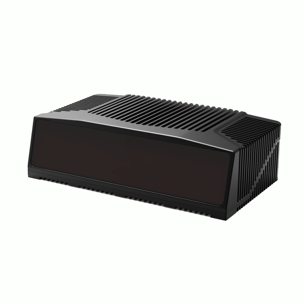
LS Lidar LS500W1 150m Ultra Wide Field of View 3D LiDAR
Get the best price for your setup
Contact our experts for the best possible price and configuration.
- Fast response
- Expert configuration advice
- No overpaying for features you do not need
The LS Lidar LS500W1 is a hybrid solid-state 3D LiDAR designed for construction machinery, autonomous systems, industrial vehicles, UAVs and other applications that need wide-area obstacle detection and dense point cloud data. Its 120° × 73° ultra-wide field of view helps cover large blind zones, while the 1550 nm laser provides a detection range of 2–60 m on 10% reflectivity targets and up to 150 m maximum. With ±2 cm ranging accuracy and approximately 3.7 million points per second, the LS500W1 can detect and profile people, vehicles, tyres, debris and surrounding structures in real time.
LS Lidar LS500W1 Highlights
| LiDAR type | Hybrid solid-state 3D LiDAR |
|---|---|
| Detection range | 2–60 m at 10% reflectivity, up to 150 m maximum |
| Range accuracy | ±2 cm |
| Field of view | 120° horizontal × 73° vertical |
| Point rate | Approx. 3.7–3.75 million points/sec |
| Laser wavelength | 1550 nm |
| Ingress protection | IP6K9K |
Valued customers:










Find RTK Networks
Search NTRIP providers and connect to reliable RTK correction services.
Description
Ultra-Wide 3D LiDAR for Construction and Autonomous Systems
The LS Lidar LS500W1 is a hybrid solid-state LiDAR developed for machines and vehicles that need a wide view of their surroundings. Its combination of a 120° horizontal and 73° vertical field of view allows a single sensor to monitor a large area, making it particularly useful for blind-spot detection, obstacle awareness and machine perception around construction equipment, autonomous vehicles and industrial systems.
Unlike a narrow single-point distance sensor, the LS500W1 produces a dense 3D point cloud. This allows a control system to determine not only how far away an object is, but also its position and approximate 3D profile. In practical field use, that makes it possible to detect people, vehicles, tyres, debris, loading material and surrounding structures within the sensor’s field of view.
Wide Field of View Helps Reduce Blind Areas
The LS500W1 covers 120° horizontally and 73° vertically. This unusually wide vertical coverage is especially useful on large machinery where obstacles may be located close to the vehicle, below the driver’s normal line of sight or around loading and working areas.
For loaders, mining trucks and other construction machinery, the wide viewing angle can help a machine perception system monitor areas that are difficult to cover with conventional cameras or narrower LiDAR sensors. The same characteristic is useful for autonomous platforms, mobile robots and industrial vehicles operating around people and equipment.
Up to 150 Metres Detection Range
The LS500W1 uses a 1550 nm Time of Flight laser system. Its specified detection range is 2 to 60 metres on targets with 10% reflectivity, with a maximum detection distance of up to 150 metres under suitable target and environmental conditions.
Reflectivity is important when comparing LiDAR range. Dark materials return less laser energy than bright or reflective surfaces, so the distance at which an object can be detected depends on the target itself as well as weather, installation angle and atmospheric conditions. For machine applications, the 60 m figure at 10% reflectivity provides a useful reference for more difficult targets, while the 150 m maximum indicates the longer-range capability available on stronger returns.
Dense Point Clouds for Object Detection and Volume Measurement
With a point generation rate of approximately 3.7 million points per second, the LS500W1 captures a large amount of spatial information within its field of view. This dense data can help software distinguish the shape and position of obstacles instead of relying on a single distance value.
One practical application is material handling. On a loader or similar machine, the 3D point cloud can be used to observe material in front of the vehicle and support functions such as pile or ore volume measurement. For autonomous and industrial applications, the same point cloud can be used for obstacle detection, environmental perception and navigation.
±2 cm Ranging Accuracy
The LS500W1 has a specified range accuracy of ±2 cm. In machine perception applications, this means the system receives consistent distance information with enough detail to locate objects and surfaces accurately within the LiDAR’s working area.
This accuracy is particularly valuable when the LiDAR is integrated with machine control, autonomous driving or monitoring software, where small errors in measured object position can affect path planning, collision avoidance or volume calculations.
Designed for Challenging Outdoor Environments
The LS500W1 is built for equipment that works outside and in industrial conditions. Its IP6K9K protection rating provides a high level of protection against dust and high-pressure water, while the specified operating temperature range extends from -40°C to +85°C.
The 1550 nm system is also intended to operate across different lighting conditions. LiDAR does not depend on ambient illumination in the same way as a conventional camera, which makes it suitable for day, night and low-light operation. Actual detection performance in rain, snow, fog or dust will still depend on the severity of the conditions and the installation.
Industrial Ethernet and Time Synchronisation
The LS500W1 communicates through Industrial Ethernet, making it suitable for integration with embedded computers, machine controllers and perception systems that need to process high-rate point cloud data. It supports GPS, PTP and gPTP time synchronisation, which is useful when LiDAR data needs to be aligned with cameras, GNSS, IMUs or other sensors.
This becomes especially important on autonomous vehicles, UAVs and mapping platforms where several sensors may be collecting data at the same time. Accurate timestamps allow software to combine those measurements correctly as the platform moves.
Suitable Applications
- Construction and mining machinery blind-spot detection
- Autonomous and driverless vehicles
- Industrial and logistics vehicles
- UAV and drone perception systems
- Security and perimeter monitoring
- Ports and automated material handling
- 3D mapping and machine perception
Integration into Machine and Mapping Systems
The LS500W1 operates from a 9–36 VDC input range and uses Industrial Ethernet for point cloud communication. The sensor measures approximately 270 × 160 × 80 mm and weighs up to 3 kg. These characteristics make it more suitable for vehicle, machinery and larger UAV integration than for lightweight handheld scanning.
For mapping and autonomous applications, the LiDAR can be combined with GNSS, IMU, cameras or other sensors to create a complete positioning and perception system. Its support for external timing makes this type of multi-sensor integration easier when accurate synchronisation is required.
Who Is the LS500W1 For?
The LS500W1 is primarily intended for engineers, integrators and machine manufacturers rather than users looking for a self-contained handheld scanner. It is a strong fit for construction equipment, mining machinery, autonomous vehicle projects, industrial automation, mapping platforms and other systems where the LiDAR becomes part of a larger hardware and software solution.
Buyers should consider the required field of view, target reflectivity, working distance, environmental conditions and data-processing requirements when selecting the sensor. Global GPS Systems can assist with product selection and integration questions when the LS500W1 is being combined with GNSS, positioning, mapping or machine-control equipment.
Specifications
LSLiDAR LS500W1 Ultra-Wide FOV 3D LiDAR Specifications
Product Overview
| Product name | LSLiDAR LS500W1 |
|---|---|
| Product type | Hybrid solid-state 3D LiDAR |
| Primary function | Wide-area 3D perception, blind-spot detection, obstacle detection and high-density point cloud generation |
| Detection principle | Time of Flight (ToF) |
| Laser source | LSLiDAR self-developed 1550 nm fiber laser |
| Scanning architecture | Hybrid solid-state |
| Scanning channels | 480 channels according to current LSLiDAR product information |
| Primary applications | Construction machinery, autonomous and driverless vehicles, industrial automation, mining, logistics, ports, security, UAV / drone systems and mapping |
Laser and Ranging Specifications
| Detection method | ToF (Time of Flight) |
|---|---|
| Laser wavelength | 1550 ±25 nm according to the LS500W1 User Manual |
| Laser class | Class 1 eye-safe |
| Detection range at 10% reflectivity | 2–60 m |
| Maximum detection range | 150 m |
| Current manufacturer published overall detection range | 2–150 m |
| Range accuracy / precision | ±2 cm |
| Laser scan lines | 4,800 lines/second according to the LS500W1 User Manual |
| Frame rate | 10 FPS / 10 Hz |
| Echo mode | Single echo; the User Manual specifies measurement of the most recent echo value |
Field of View and Angular Resolution
| Horizontal field of view | 120° |
|---|---|
| Vertical field of view | 73° |
| Vertical angular coverage | Approximately ±36.5° |
| Horizontal angular resolution | 0.155° |
| Vertical angular resolution | 0.146° |
| Resolution reference frame rate | 10 Hz |
| Combined FOV | 120° × 73° (H × V) |
Point Cloud Performance
| Current manufacturer published point rate | Up to 3,700,000 points/second |
|---|---|
| User Manual point rate | 3,750,000 points/second |
| Scanning channels | 480 |
| Point cloud type | High-density 3D point cloud |
| Point cloud information | Distance, horizontal / vertical angle, intensity, timestamp and calculated 3D coordinates |
| Cartesian output processing | Polar ranging information can be converted into X, Y and Z coordinates using the coordinate model documented by LSLiDAR |
| Small-object detection | Designed to detect objects including people, animals, vehicles, tires and debris |
| Low-reflectivity target capability | 1550 nm architecture is designed for improved detection of low-reflectivity and dark targets |
Electrical Specifications
| Input voltage range | 9–36 VDC |
|---|---|
| Power supply note | The User Manual states that 9 V and 36 V are short-term extreme supply limits and should not be treated as normal continuous working voltages |
| Power consumption | ≤40 W |
| Power interface | M12 A-coded 12-pin interface |
| Power connector supplier reference | L102-M12-Z12A23B according to the User Manual |
| Power / synchronization cable | 12-pin power supply and GPS synchronization cable |
Communication Interface
| Primary data interface | Industrial Ethernet |
|---|---|
| Ethernet physical interface | M12 X-coded 8-pin |
| Ethernet speed | 1000BASE-T / Gigabit Ethernet wiring documented in the User Manual |
| Ethernet cable host connector | Shielded RJ45 8P8C Cat.6 |
| Ethernet LiDAR connector | M12 X-coded 8-pin male |
| Transport protocol | UDP/IP |
| Packet byte order | Big-endian for MSOP data |
Network Configuration
| Default LiDAR IP address | 192.168.1.200 |
|---|---|
| Default host computer IP | 192.168.1.102 |
| Default LiDAR device packet port | 2368 |
| Default LiDAR data packet port | 2369 |
| Default computer device packet port | 2369 |
| Default computer data packet port | 2368 |
| IP configuration | LiDAR and destination IP parameters can be reconfigured through the documented device configuration protocol |
| Multicast configuration | Supported within the documented network-address restrictions |
UDP Communication Protocols
| Protocol | Function | Transmission |
|---|---|---|
| MSOP | Main Data Stream Output Protocol; outputs measured point-cloud data and timestamps | Approximately 0.06712 ms packet interval |
| DIFOP | Device Information Output Protocol; outputs device configuration and status information | 1 packet per second |
| UCWP | User Configuration Write Protocol; writes configurable LiDAR parameters | Variable |
MSOP Point Cloud Data
| Total Ethernet packet length | 1248 bytes |
|---|---|
| Ethernet header | 42 bytes |
| Payload | 1206 bytes |
| Point cloud payload | 1192 bytes |
| Additional information | 14 bytes |
| Additional data content | Reserved data, UTC, timestamp, data type and hardware identifier |
| Distance information | Included |
| Angle information | Included |
| Intensity information | Included |
| Timestamp | Included |
Time Synchronization
| Supported clock sources | GPS, PTP and gPTP |
|---|---|
| Internal timing | Supported when no external synchronization source is available |
| GPS synchronization | Supported using PPS plus GPS serial data |
| GPS time message | NMEA $GPRMC |
| GPS serial baud rate | 9600 baud |
| GPS serial format | 8 data bits, 1 stop bit, no parity |
| GPS interface electrical levels | TTL and RS-232 variants documented |
| RS-232 PPS level | 3.0–15.0 V |
| Minimum PPS high pulse width | Greater than 1 ms |
| PTP | Supported |
| gPTP | Supported |
| PTP transport | MAC or IPv4; IPv6 is not supported by the documented implementation |
| PTP mode | Peer-to-Peer (P2P) |
| PTP synchronization method | Two-Step |
| PTP synchronization accuracy | Sub-microsecond-class synchronization according to the manufacturer documentation |
| Timestamp resolution | Nanosecond timing is documented for synchronized point-cloud data |
GPS / INS Integration
| External GPS support | Supported for time synchronization |
|---|---|
| GPS PPS input | Supported |
| GPS serial input | Supported |
| Latitude / longitude information | Parsed from compatible GPS data and available within device information |
| UTC synchronization | Supported through GPS |
| INS integration use | Precise point-cloud timing can be associated with external pitch, roll, yaw, latitude, longitude and height data from a GPS / inertial measurement system |
Software and Driver Support
| Windows support | Supported |
|---|---|
| Linux support | Supported through the LSLiDAR ROS driver |
| Windows point cloud software | LSLiDAR Upper Computer Platform / point cloud display software |
| Linux driver | ROS Driver Program |
| Windows architecture | x64 |
| Packet analysis | Wireshark can be used for ARP / network packet discovery and diagnostics |
| Windows packet capture dependency | Npcap required by the documented Upper Computer Platform |
| Point cloud viewing | Supported in the Windows client and ROS-compatible visualization workflows |
| Parameter configuration | Supported through the manufacturer host software |
| LiDAR test functions | Supported through the manufacturer host software |
Host Computer Requirements
| Component | Manufacturer Requirement / Recommendation |
|---|---|
| Operating system | 64-bit Windows for the LSLiDAR Upper Computer Platform |
| Processor | Intel Core i5 or higher |
| Graphics | NVIDIA GeForce GTX 750 or higher recommended by the User Manual for effective point cloud display |
| Network interface | Compatible Ethernet adapter capable of communicating with the LiDAR's industrial Ethernet interface |
| Linux environment | Compatible ROS environment for the supplied LSLiDAR ROS driver |
Environmental Specifications
| Ingress protection | IP6K9K |
|---|---|
| Operating temperature | -40°C to +85°C |
| Storage temperature | -40°C to +105°C |
| Shock resistance | 500 m/s² for 11 ms |
| Approximate shock level | Approximately 51 g |
| Vibration resistance | 5–2000 Hz, 3 g RMS |
| Rain operation | Designed for operation in challenging weather conditions |
| Snow operation | Designed for operation in challenging weather conditions |
| Fog operation | Designed for operation in challenging weather conditions |
| Lighting conditions | 1550 nm LiDAR architecture is designed for operation across changing ambient-light conditions |
Physical Specifications
| Length | 270 mm |
|---|---|
| Width | 160 mm |
| Height | 80 mm |
| Overall dimensions | 270 × 160 × 80 mm |
| Weight | ≤3 kg |
| Location / alignment pins | 2 × Ø3 mm dowel-pin location holes documented in the mechanical mounting drawing |
| Mounting fasteners | 4 × M5 × 6 mm hexagon socket-head cap screws documented for mounting and fixing |
Laser Safety
| Laser safety classification | Class 1 |
|---|---|
| IEC standard | IEC 60825-1:2014 |
| US laser safety compliance | 21 CFR 1040.10 and 1040.11, subject to the deviations referenced by the manufacturer |
| Optical viewing warning | Do not directly view the transmitting laser through magnifying optical equipment |
| Housing requirement | Operate only with the product housing correctly secured |
| User disassembly | Not permitted by the manufacturer |
Target Detection and Perception Features
| Pedestrian detection | Supported application |
|---|---|
| Animal detection | Supported application |
| Vehicle detection | Supported application |
| Tire detection | Supported application |
| Debris / fallen object detection | Supported application |
| Blind-spot coverage | Ultra-wide 120° × 73° FOV designed to minimize blind areas around machinery and vehicles |
| 3D profile output | Supported |
| Distance output | Supported |
| Ore / material volume monitoring | High-density point cloud can be used for real-time material-volume measurement applications on compatible construction and mining equipment |
Typical Applications
| Application | Typical LS500W1 Function |
|---|---|
| Construction machinery | Blind-spot monitoring, obstacle detection and surrounding 3D perception |
| Mining equipment | Obstacle detection and high-density point-cloud-based material / ore volume measurement |
| Autonomous vehicles | Wide-FOV environmental perception and small-object detection |
| Industrial automation | 3D object and environment detection |
| Logistics | Object, vehicle and environment perception |
| Ports | Equipment safety, obstacle detection and automation support |
| Security | Wide-area 3D detection and monitoring |
| UAV / drone | 3D perception and mapping integration where payload, power and interface requirements are suitable |
| Mapping | High-density 3D point cloud acquisition with external position / orientation synchronization |
Documentation and Specification Notes
| User Manual researched | LS500W1 User Manual V1.0.3, October 2024 |
|---|---|
| Manufacturer current product page | LS500W1 Ultra-Wide FOV Blind Spot Detection LiDAR |
| Point-rate documentation difference | The V1.0.3 User Manual specifies 3,750,000 points/s, while the current LSLiDAR product page specifies 3,700,000 points/s |
| Scanning-channel documentation | Current manufacturer product information describes 480 scanning channels; the User Manual separately specifies 4,800 laser scan lines per second |
| Echo documentation | The LS500W1 User Manual V1.0.3 specifies single-echo operation |
| Integration note | Exact network, synchronization and electrical configuration should be matched to the production hardware revision and host system before integration |
Specifications and package contents may vary by configuration, region or manufacturer update. Always check the current configuration before ordering.
Reviews (0)
Only logged in customers who have purchased this product may leave a review.
FAQ
LS LiDAR LS500W1 FAQ
LS500W1 LiDAR & Applications
What is the LS LiDAR LS500W1?
The LS LiDAR LS500W1 is a hybrid solid-state 3D LiDAR sensor designed for wide-area object detection, environmental perception and high-density point cloud generation. It combines a 1550 nm Time of Flight laser system with a 120° horizontal and 73° vertical field of view, making it suitable for applications such as construction machinery, autonomous systems, industrial automation, logistics, mapping and safety monitoring.
Is the LS500W1 a 3D LiDAR scanner?
Yes. Unlike a single-point laser distance sensor, the LS500W1 measures across a wide two-dimensional field of view and produces dense 3D point cloud data. It can generate up to approximately 3.75 million points per second, allowing the shape, position and distance of objects within its viewing area to be detected.
What is a hybrid solid-state LiDAR?
A hybrid solid-state LiDAR uses an optical scanning architecture that reduces reliance on the large rotating assemblies found in traditional mechanical 360-degree LiDAR sensors. The LS500W1 uses this approach to provide a fixed 120° × 73° field of view for applications where the sensor is installed facing a specific area around a vehicle, machine or monitoring system.
What can the LS500W1 be used for?
Typical LS500W1 applications include blind-spot detection on construction and mining machinery, autonomous and driver-assistance systems, industrial automation, logistics, ports, security systems, UAV or drone integration and mapping. Its wide field of view is particularly useful when a large area needs to be monitored with a single sensor.
Can the LS500W1 detect people, vehicles and small obstacles?
Yes. The LS500W1 is designed to detect objects including people, animals, vehicles, tyres, debris and other obstacles within its measurement area. It outputs distance and 3D profile information that can be processed by perception or safety software to identify objects and their position relative to the sensor.
Can the LS500W1 be used on construction and mining machinery?
Yes. Construction and mining machinery are important applications for the LS500W1. Its wide field of view can monitor blind spots around loaders and other large equipment, while the dense point cloud can also be used by suitable software to measure material or ore volumes in front of the machine.
Range, Accuracy & Point Cloud Performance
What is the detection range of the LS LiDAR LS500W1?
The LS500W1 has a maximum specified detection range of approximately 150 metres. The manufacturer specifies approximately 2 to 60 metres when measuring a target with 10% reflectivity. Actual range depends on target reflectivity, atmospheric conditions, target angle and the operating environment.
How accurate is the LS500W1?
The LS500W1 has a specified range accuracy of approximately ±2 cm under suitable operating conditions. This specification relates to the LiDAR's distance measurement. The accuracy of a complete mapping or positioning system can also depend on calibration, mounting, synchronization and any GNSS or inertial navigation equipment used with the sensor.
What is the field of view of the LS500W1?
The LS500W1 provides a 120° horizontal field of view and a 73° vertical field of view. The large vertical and horizontal coverage allows the sensor to monitor a broad area without requiring a mechanically rotating 360-degree scanner.
What is the angular resolution of the LS500W1?
The specified angular resolution is approximately 0.155° horizontally and 0.146° vertically at its standard 10 Hz operating mode. This dense angular sampling contributes to the detailed 3D point cloud generated by the sensor.
How many points per second does the LS500W1 generate?
The LS500W1 can generate approximately 3.75 million point measurements per second. This high point rate allows the sensor to capture detailed object contours and environmental geometry for perception, measurement and mapping applications.
What is the frame rate of the LS500W1?
The LS500W1 operates at a specified frame rate of 10 frames per second. This allows the 3D scene to be updated repeatedly in real time, which is important for applications involving moving vehicles, machinery, people or other dynamic objects.
Laser, Connectivity & System Integration
What laser wavelength does the LS500W1 use?
The LS500W1 uses a 1550 nm fibre laser, specified at 1550 ±25 nm. The sensor uses Time of Flight technology, measuring the travel time of emitted laser pulses and their reflections to determine the distance and position of objects.
Is the LS500W1 laser eye-safe?
Yes. The LS500W1 is specified as a Class 1 eye-safe laser product. It should still be installed, operated and maintained according to the manufacturer's laser-safety instructions, and the optical window should not be modified or disassembled.
How does the LS500W1 connect to a computer or control system?
The LS500W1 uses an industrial Ethernet connection for data communication. Point cloud data, timestamps, sensor status and configuration information are transferred using Ethernet-based UDP/IP communication, allowing the LiDAR to be integrated with industrial computers, autonomous controllers and other processing platforms.
Can the LS500W1 be used with Windows and Linux?
Yes. The manufacturer's software workflow supports operation with Windows, and a ROS driver is available for Linux-based development environments. This allows the LS500W1 to be integrated into both conventional PC applications and robotics or autonomous-system workflows.
Does the LS500W1 support GPS or PTP time synchronization?
Yes. The LS500W1 supports GPS-based synchronization as well as PTP and gPTP timing. Accurate synchronization is important when combining LiDAR measurements with GNSS, IMU, cameras or other sensors in mapping, robotics and autonomous-machine applications.
Can the LS500W1 be used for georeferenced LiDAR mapping?
Yes, as part of a complete mapping system. The LS500W1 produces high-density 3D measurements relative to the sensor itself. To generate accurately georeferenced point clouds from a moving vehicle, UAV or other platform, it normally needs to be integrated with suitable GNSS and inertial navigation equipment together with calibration, synchronization and processing software.
Power, Durability & Installation
What power supply does the LS500W1 require?
The LS500W1 accepts a nominal input range of 9 to 36 VDC and has specified power consumption of up to approximately 40 W. The manufacturer notes that the extreme ends of the voltage range are intended for short-term conditions, so the installation should use an appropriate stable working supply according to the user manual.
Is the LS500W1 waterproof and dustproof?
The LS500W1 has an IP6K9K environmental protection rating. This provides a high level of protection against dust and high-pressure, high-temperature water jets, making the sensor suitable for installation on machinery and vehicles operating in demanding outdoor environments.
What temperature range can the LS500W1 operate in?
The specified operating temperature range is approximately -40°C to +85°C, with a specified storage range of approximately -40°C to +105°C. This wide temperature range is intended to support vehicle, industrial and outdoor applications in demanding environments.
Is the LS500W1 resistant to vibration and shock?
Yes. The LS500W1 is designed for mobile and industrial installations. The manufacturer specifies vibration testing from 5 Hz to 2000 Hz at 3G RMS and shock testing of 500 m/s² for 11 ms, helping the sensor withstand the vibration and impacts associated with machinery and vehicle applications.
How large and heavy is the LS500W1?
The LS500W1 measures approximately 270 × 160 × 80 mm and weighs no more than approximately 3 kg. Its fixed sensor housing is designed for permanent integration onto vehicles, machines or other measurement platforms.
What should be considered when installing the LS500W1?
The sensor should be mounted securely using the specified mounting points, with sufficient heat dissipation and an unobstructed view through the optical window. The mounting angle should match the required detection area, and installations used for measurement or mapping should also account for sensor alignment and calibration relative to any GNSS, IMU, camera or vehicle coordinate system.
 GPS & GNSS
 Total Stations
 Data collectors
 Software
 Correction services
 Machine control
 External radio
 Marine
 Accessories
Reviews
There are no reviews yet